Desulphurization pump impeller of novel structure

A new type of structure, desulfurization pump technology, applied in the components, pumps, pump components of the pumping device for elastic fluid, etc., can solve the problems of difficult assembly and disassembly, poor balance effect, easy damage and so on

Inactive Publication Date: 2014-01-15
SHANGHAI LIANCHENG(GRP) CO LTD
View PDF6 Cites 3 Cited by
  • Summary
  • Abstract
  • Description
  • Claims
  • Application Information

AI Technical Summary

Problems solved by technology

[0002] For traditional desulfurization pump impellers, most of them follow the structure of ordinary centrifugal pump impellers, which are closed structures in which the front cover, rear cover and blades are cast together (such as figure 1 As shown), the disadvantages of the impeller of this structure are listed as follows: the impeller flow channel is formed by casting, the surface finish is poor, and the efficiency is low; the integral casting structure has large casting deviation and low dimensional accuracy; the integral casting structure has large dimensional deviation, The strength is low, so it is necessary to leave a large size margin, and the material is wasted; the entire impeller can only be made of one material, and the cost is high; the blades of the impeller of the desulfurization pump are easily damaged, and once the blades are damaged, the entire impeller needs to be replaced, resulting in waste of materials , high maintenance cost; the balance hole is used to balance the axial force, the balance effect is poor, and it affects the flow state of the impeller inlet, and the efficiency is low; the inner hole of the impeller hub is threaded, and the thread is more demanding than the smooth hole processing, requiring the production of special tools and measuring tools , the processing cost is high; the connection between the impeller and the shaft is a threaded connection, which is difficult to assemble and disassemble, resulting in high assembly and maintenance costs

Method used


Image

  • Desulphurization pump impeller of novel structure
  • Desulphurization pump impeller of novel structure
  • Desulphurization pump impeller of novel structure

Examples


Embodiment Construction

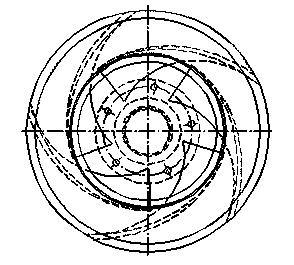
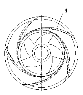
[0007] The figure includes the impeller rear cover, the blades, and the impeller front cover. The blades are installed in the impeller channel formed between the impeller rear cover and the impeller front cover. The front cover auxiliary blades and rear cover auxiliary blades are located on the front and rear sides of the blade respectively. The front cover auxiliary blades The blades and the rear cover plate auxiliary blades extend out of the front cover plate of the impeller and the rear cover plate of the impeller respectively. It is characterized in that the blade, the impeller rear cover plate and the impeller front cover plate are welded and connected to each other. It is characterized in that: the inner hole of the hub of the impeller is a light hole.

[0008] The impeller rear cover and impeller front cover are not easy to damage and can be made of materials with lower requirements. The blades are easy to be damaged and can be made of higher requirements. Road and bl...


PUM


Abstract

The invention relates to a desulphurization pump impeller of a novel structure. The desulphurization pump impeller comprises an impeller rear covering board, blades and an impeller front covering board. The desulphurization pump impeller is characterized in that the blades are provided with front covering board secondary blades and rear covering board secondary blades, the impeller rear covering board and the impeller front covering board are provided with blade grooves, each front covering board secondary blade and each rear covering board secondary blade which are both arranged on the blades are located on the front side and the rear side of each blade respectively, and the front covering board secondary blades and the rear covering board secondary blades stretch out of the impeller front covering board and the impeller rear covering board respectively; the blades, the impeller rear covering board and the impeller front covering board are connected with one another in a welded mode; an impeller hub inner hole is an unthreaded hole. The desulphurization pump impeller of the novel structure has the advantages that the front covering board, the rear covering board and the blades are mutually independent, and therefore the front covering board, the rear covering board and the blades can be manufactured independently and made of different materials; when the blades are damaged, the blades can be replaced independently, the whole impeller does not need to be replaced, and the blades of the impeller are provided with the front secondary blades and the rear secondary blades so that axial force can be balanced.

Description

technical field [0001] The invention relates to a desulfurization pump impeller with a new structure. Background technique [0002] For traditional desulfurization pump impellers, most of them follow the structure of ordinary centrifugal pump impellers, which are closed structures in which the front cover, rear cover and blades are cast together (such as figure 1 As shown), the disadvantages of the impeller of this structure are listed as follows: the impeller flow channel is formed by casting, the surface finish is poor, and the efficiency is low; the integral casting structure has large casting deviation and low dimensional accuracy; the integral casting structure has large dimensional deviation, The strength is low, so it is necessary to leave a large size margin, and the material is wasted; the entire impeller can only be made of one material, and the cost is high; the blades of the impeller of the desulfurization pump are easily damaged, and once the blades are dama...

Claims


Application Information

Patent Timeline
Patent Type & Authority Applications(China)
IPC IPC(8): F04D29/22
Inventor 张培富张锡淼
Owner SHANGHAI LIANCHENG(GRP) CO LTD
Why Eureka
Try Eureka