

Gear device with inertia structure
A technology of gear device and inertia wheel, which is applied in the direction of gear transmission device, electromechanical device, transmission device, etc., can solve the problems of insufficient load and torque application requirements, and limited load, so as to increase torque, save electric energy, and increase load The effect of endurance
- Summary
- Abstract
- Description
- Claims
- Application Information
AI Technical Summary
Problems solved by technology
Method used
Image

Examples
Embodiment 1
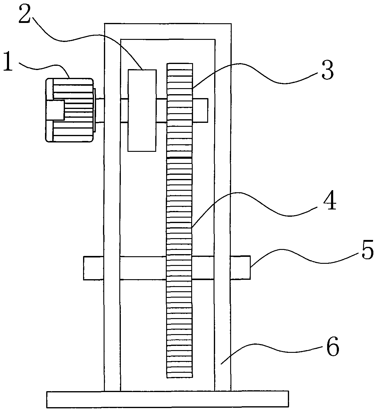
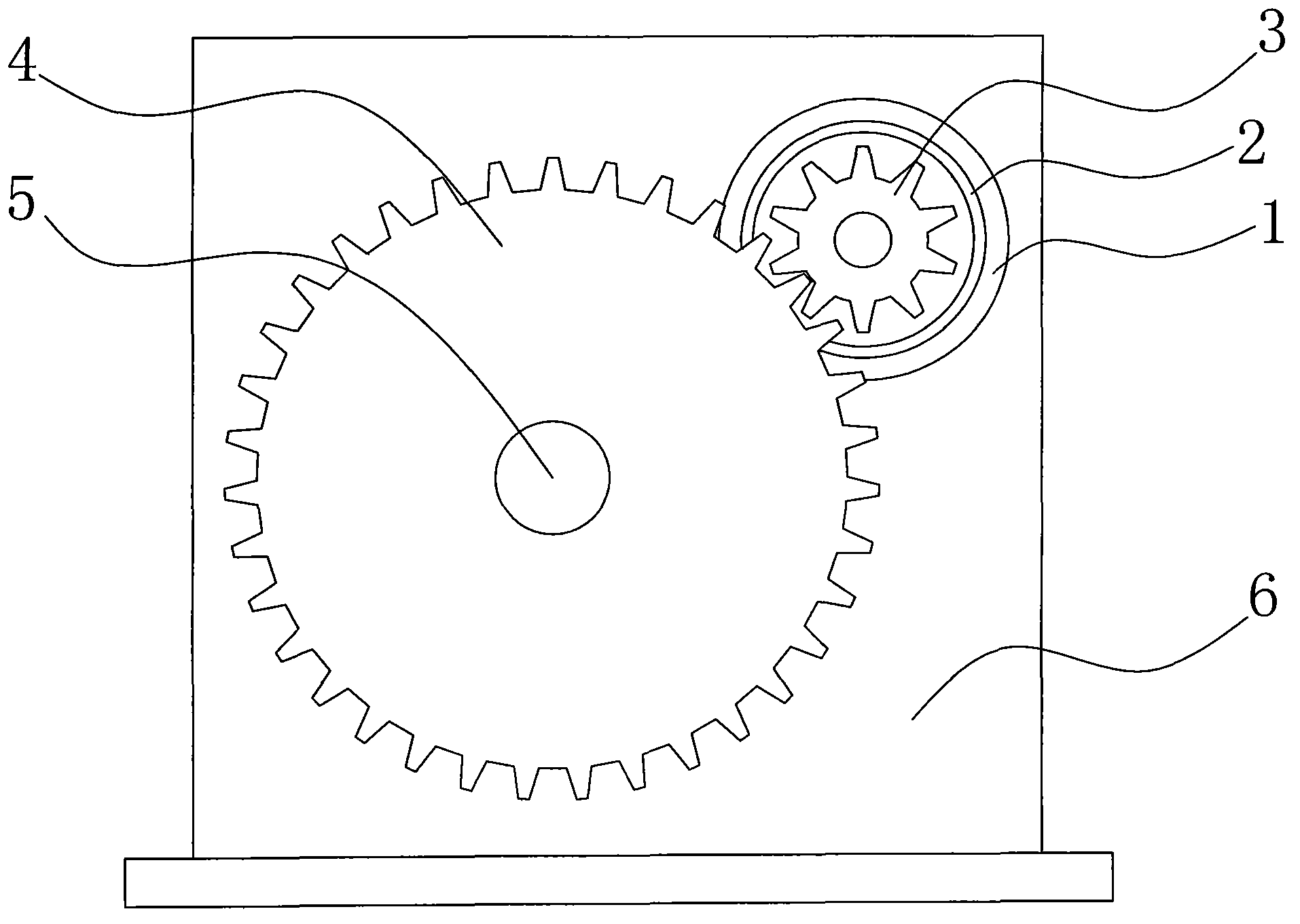
[0024] combine figure 1 and figure 2 As shown, a gear device with an inertial structure of the present invention includes a pinion 3 connected to the motor 1, a large gear 4 meshed with the pinion 3, an output shaft 5 is connected to the large gear 4, and the large gear 4 is connected to the small gear 4. The speed ratio of gear 3 is more than 5 times, wherein, between motor 1 and pinion 3, connect clutch or speed change device 2, as preferred embodiment, get clutch or speed changer as clutch or speed change device 2. This gear structure also includes a shaft support 6, the output shaft of the motor 1 and the output shaft 5 connected with the bull gear 4 are connected on the shaft support 7 through bearings, and the motor 1 is arranged on the outside of the shaft support 7.
[0025] As a preferred embodiment, the motor 1 selects a high-speed motor whose rotation speed is above 3500 r / min.
[0026] The gear device with inertial structure of the present invention is used for ...
Embodiment 2
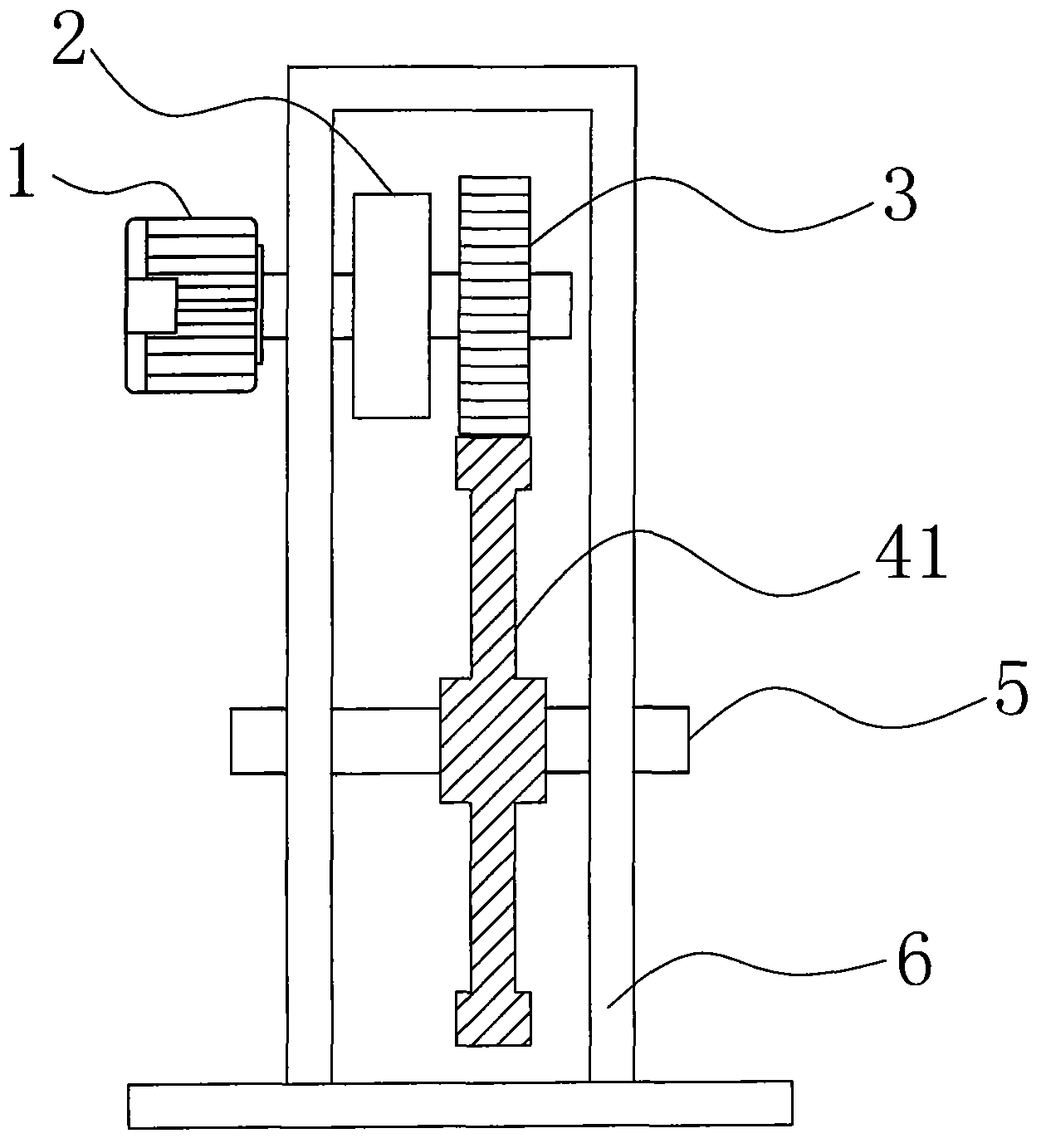
[0028] combine Figure 3 to Figure 5 As shown, a gear device with an inertial structure of the present invention includes a pinion 3 connected to the motor 1, a large gear 4 meshed with the pinion 3, an output shaft 5 is connected to the large gear 4, and the large gear 4 is connected to the small gear 4. The speed ratio of gear 3 is more than 5 times, wherein, between motor 1 and pinion 3, connect clutch or speed change device 2, as preferred embodiment, get clutch or speed changer as clutch or speed change device 2. This gear structure also includes a shaft support 6, the output shaft of the motor 1 and the output shaft 5 connected with the bull gear 4 are connected on the shaft support 7 through bearings, and the motor 1 is arranged on the outside of the shaft support 7.
[0029] Also be provided with at least one fly wheel 7 on the output shaft that connects bull gear 4, be arranged on the inside or outside of shaft support 7 all can. Such as image 3 As shown in , the i...
Embodiment 3
[0032] combine Figure 6 As shown, a gear device with an inertial structure of the present invention includes a pinion 3 connected to the motor 1, a large gear 4 meshed with the pinion 3, an output shaft 5 is connected to the large gear 4, and the large gear 4 is connected to the small gear 4. The speed ratio of gear 3 is more than 5 times, wherein, between motor 1 and pinion 3, connect clutch or speed change device 2, as preferred embodiment, get clutch or speed changer as clutch or speed change device 2. This gear structure also includes a shaft support 6, the output shaft of the motor 1 and the output shaft 5 connected with the bull gear 4 are connected on the shaft support 7 through bearings, and the motor 1 is arranged on the outside of the shaft support 7.
[0033] A plurality of pinion gears 3 are provided to mesh with the bull gear 4 , and each pinion gear 3 is connected to the motor 1 through a clutch or a transmission 2 .
[0034] As an embodiment, two pinion gears ...
PUM
 Abstract
Description
Claims
Application Information