
Large face automatic measurement method based on laser tracker

A technology of a laser tracker and a measurement method, applied in the field of laser measurement, can solve the problems of large measurement workload, low target positioning accuracy, inability to achieve target standard positioning, etc., and achieves the effects of low manufacturing cost, increased investment, and high measurement accuracy.

Inactive Publication Date: 2014-01-15
NANJING UNIV OF AERONAUTICS & ASTRONAUTICS +1
View PDF4 Cites 18 Cited by
  • Summary
  • Abstract
  • Description
  • Claims
  • Application Information

AI Technical Summary

Benefits of technology

This new technology allows companies to quickly test different types of materials more accurately than previous methods or reduce their costs by measuring them on several locations instead of just one location. Additionally it makes measurements faster without requiring any extra equipment like an oscilloscope.

Problems solved by technology

Technological Problems addressed in this patented technical problem include the limitations associated with current methods like manually operated tools or opaque markers due to their weightiness and limited usages when trying to perform complicated measurements involving large parts. Additionally, existing methods often result in errors caused by human factors including subjectivity and repetitive movements over many hours.

Method used


Image

  • Large face automatic measurement method based on laser tracker
  • Large face automatic measurement method based on laser tracker
  • Large face automatic measurement method based on laser tracker

Examples


Embodiment Construction

[0029] The present invention will be further described below in conjunction with accompanying drawing:

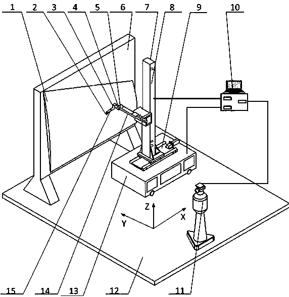
[0030] Such as figure 1 As shown, the product 1 to be tested is clamped by the tooling 6, and the tooling is firmly supported on the ground 12. The automatic measuring device adopted in this method comprises a rectangular three-coordinate servo mechanism 7, a computer control system 10, a laser tracker 11, and a navigation dolly 13; The clamping mechanism 15 is composed; the end of the clamping mechanism 15 clamps the target 2, and can move along the sliding table 9, the feeding mechanism 14, and the column 8 respectively in the X direction, the Y direction, and the Z direction. A spring 3, a pressure signal switch 4 and a limit switch 5 are installed at the connection between the clamping mechanism 15 and the feeding mechanism 14. The spring 3 is used for buffering when the target 2 touches the product 1, and the pressure signal switch 4 is used for sensing the target. 2...


PUM


Abstract

The invention relates to a large face automatic measurement method based on a laser tracker. According to the method, a navigation trolley is used as a carrier of a right-angle three-coordinate servo mechanism, theoretical data of a product to be tested are extracted, a route is planned and optimized, the laser tracker is used for setting up a coordinate system in the three-axis direction of the right-angle three-coordinate servo mechanism, relationship of the coordinate and a product coordinate system is set up through transformation of the coordinates, extracted product theoretical data coordinates are transformed to a right-angle three-coordinate system through the least square method, so that automatic operation of the right-angle three-coordinate servo mechanism is controlled, and continuous, high-accuracy and efficient measurement of the product on multi-position is achieved.

Description


Claims


Application Information

Patent Timeline
Owner NANJING UNIV OF AERONAUTICS & ASTRONAUTICS
Features
  • Generate Ideas
  • Intellectual Property
  • Life Sciences
  • Materials
  • Tech Scout
  • Unparalleled Data Quality
  • Higher Quality Content
  • 60% Fewer Hallucinations
Learn More