Chip card retaining structure

A chip card and card holding block technology, which is used in the installation of support structures, card reinforcement plates, and slidable card brackets, etc., can solve the problems of inconvenient to pull the cover, damage to the cover, and inconvenience for users to pick and place the chip card.

Inactive Publication Date: 2014-01-15
SHENZHEN FUTAIHONG PRECISION IND CO LTD
View PDF8 Cites 21 Cited by
  • Summary
  • Abstract
  • Description
  • Claims
  • Application Information

AI Technical Summary

Problems solved by technology

[0004] However, in order to prevent dust and look beautiful, the cover is generally tightly fastened with the side wall of the mobile phone casing, and the cover is generally made of hard plastic material, which is not convenient

Method used


Image

  • Chip card retaining structure
  • Chip card retaining structure
  • Chip card retaining structure

Examples


Embodiment Construction

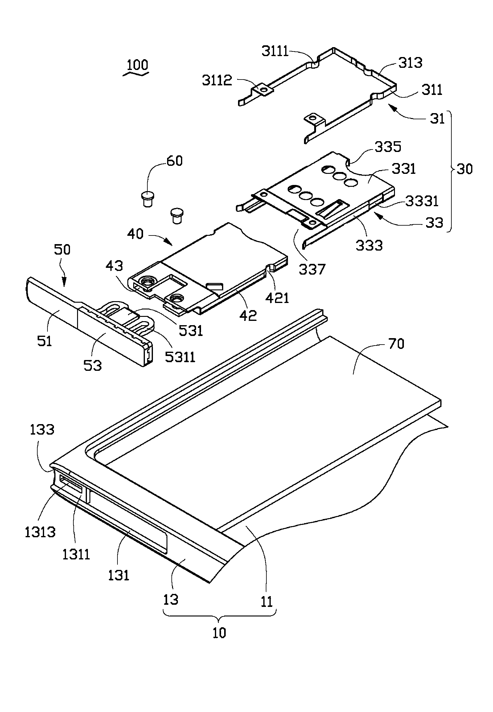
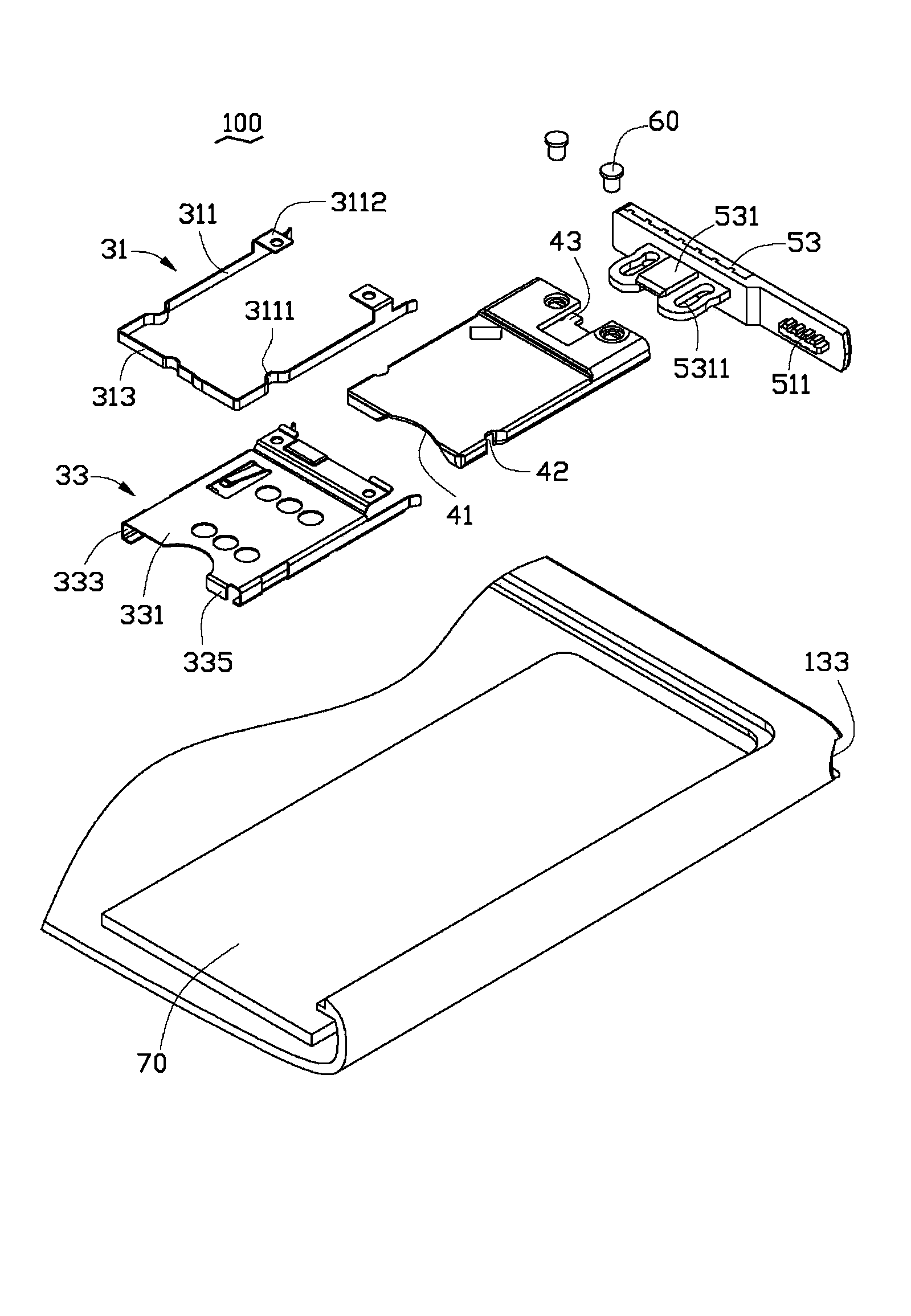
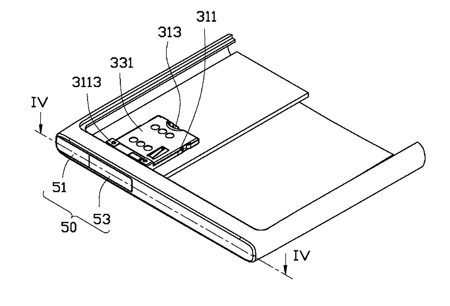
[0014] see Figure 1 to Figure 3 , the chip card holding structure 100 of the preferred embodiment of the present invention is applied to portable electronic devices such as mobile phones for fixing a chip card (not shown in the figure), and the chip card can be a SIM card or a memory card.

[0015] The chip card holding structure 100 includes a main body 10 , a positioning component 30 fixed in the main body 10 , a tray 40 detachably positioned by the positioning component 30 , and a cover plate 50 fixed on the tray 40 .

[0016] The main body 10 may be a part of the casing of the portable electronic device, or may be separately molded and fixed to the casing of the portable electronic device. In this embodiment, the main body 10 is a part of the portable electronic device. The main body 10 includes a bottom wall 11 and a peripheral wall 13 protruding around the bottom wall 11 . A mounting hole 131 is defined through the peripheral wall 13 . The installation hole 131 is us...


PUM


Abstract

The invention discloses a chip card retaining structure which comprises a body, a tray and a cover plate, wherein the tray is used for bearing a chip card, the cover plate is fixed to one end of the tray, an installing hole and a concave port communicated to the installing hole are formed in the body, the tray enters and exits the interior of the body through the installing hole, the cover plate is separably contained in the installing hole, the cover plate comprises an operation plate made of elastic materials and a fixing board fixed to the operation plate, the fixing board is connected to the tray, and the operation plate is arranged by adjoining the concave port. The chip card retaining structure is made of the elastic materials, and a user can operate the chip card retaining structure conveniently.

Description

technical field [0001] The invention relates to a chip card holding structure, in particular to a chip card holding structure applied to portable electronic devices. Background technique [0002] Most mobile phones on the market design the chip card fixing structure under the battery, but this structure is not suitable for the trend of thinning mobile phones, and the SIM card is prone to collision and wear due to frequent battery replacement. In order to overcome the above shortcomings, some mobile phones on the market design the chip card fixing structure as a drawer type, which makes full use of the existing but unused space in the mobile phone, and also solves the defect that the SIM card is easily damaged due to frequent battery replacement . [0003] The existing drawer-type chip card fixing structure usually includes a tray for carrying the chip card, and a cover plate is arranged on the tray, and the tray is pulled out from the mobile phone by pulling the cover plate...

Claims


Application Information

Patent Timeline
IPC IPC(8): H01R13/629H01R13/639H01R13/46H01R12/71
CPCH04B1/3816H04M1/026H05K5/0286H05K5/0217G06K7/003G06K13/06G06K13/085H05K7/1461
Inventor 钟焕章梁华祥
Owner SHENZHEN FUTAIHONG PRECISION IND CO LTD
Why Eureka
Try Eureka