Light emitting diode control devices and related control methods

A technology of light-emitting diodes and control devices, which is applied in the field of light-emitting diode control devices, can solve the problems of flickering users, light-emitting diodes that are difficult to achieve dimming, inconvenience, etc., to achieve reduced complexity, better linearity of dimming, and avoid discomfort Effect

Inactive Publication Date: 2014-01-15
RICHTEK TECH
View PDF4 Cites 0 Cited by
  • Summary
  • Abstract
  • Description
  • Claims
  • Application Information

AI Technical Summary

Problems solved by technology

Therefore, in the phase cut-off dimming system, when dimming the light-emitting diode, if the part of the signal that is cut off is too small (or the conduction angle is large), the function of the stable voltage or stable current in the light-emitting diode control device Compensation will be carried out so that the voltage or current applied to the LED will hardly change, so that the brightness of the LED will hardly change, so the function of dimming cannot be achieved
When the conduction angle is large, it will be difficult to achieve the dimming function by using a phase-cut dimmer with a light-emitting diode, and the dimming effect can only be achieved in the range of a small conduction angle.
Therefore, the dimming linearity of the LED light source system is not good, and the user cannot accurately adjust the light, which will cause inconvenience
[0005] In addition, when using phase-cut dimmers with LEDs for dimming, during the period when the input signal is cut off, the LED control device is not powered, but when the input signal is no longer cut off, some of the LED control device The circuit will restart operation, so during the period of restart operation, the voltage or current supplied to the LED is quite different from that before the input signal is cut off, which will also cause the linearity of dimming of the LED light source system to vary. Good, in severe cases, it will cause light flickering and cause discomfort to users

Method used


Image

  • Light emitting diode control devices and related control methods
  • Light emitting diode control devices and related control methods
  • Light emitting diode control devices and related control methods

Examples


Embodiment Construction

[0022] The embodiments of the present invention will be described below in conjunction with the relevant drawings. In these drawings, the same reference numerals indicate the same or similar elements or processes / steps.

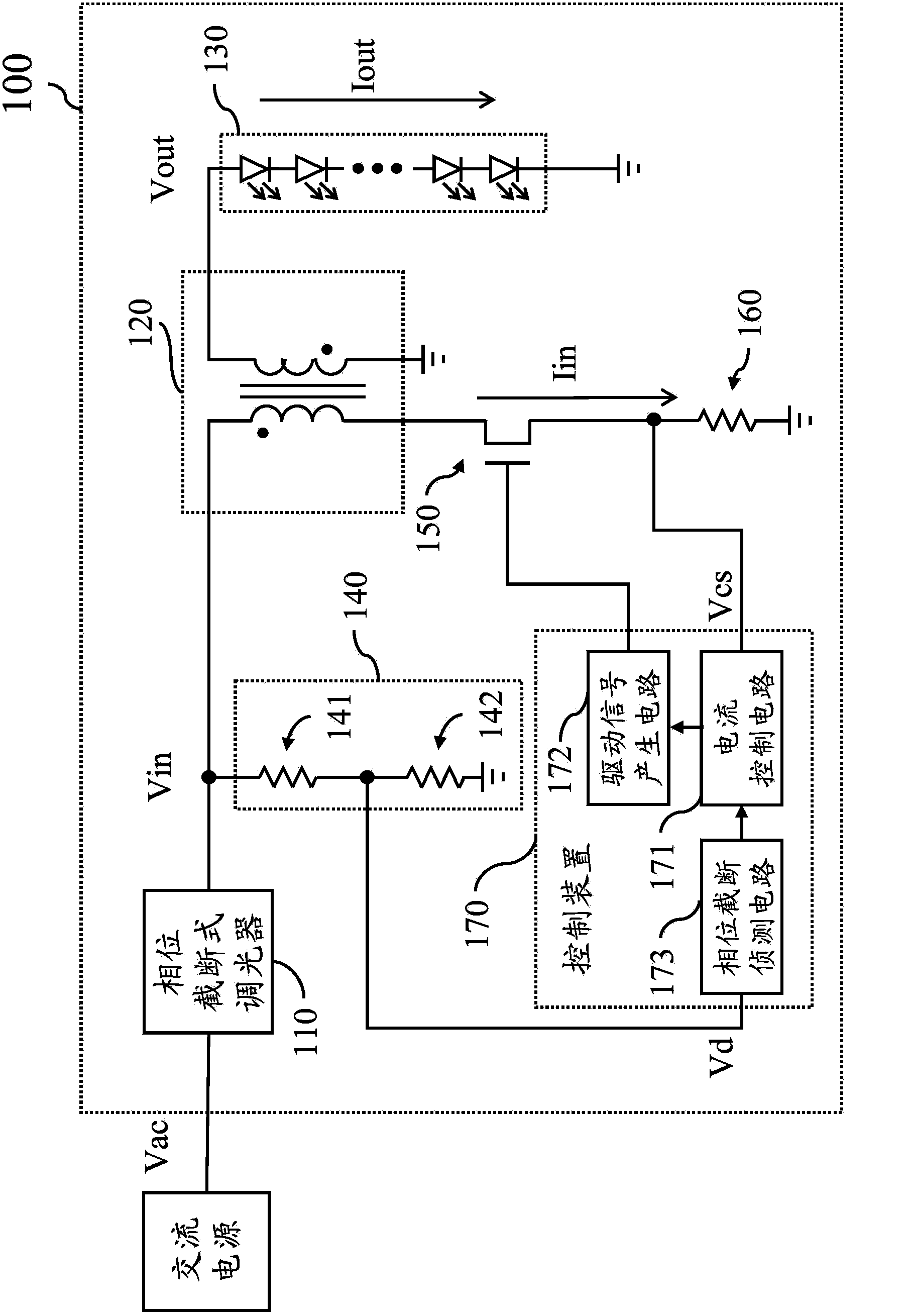
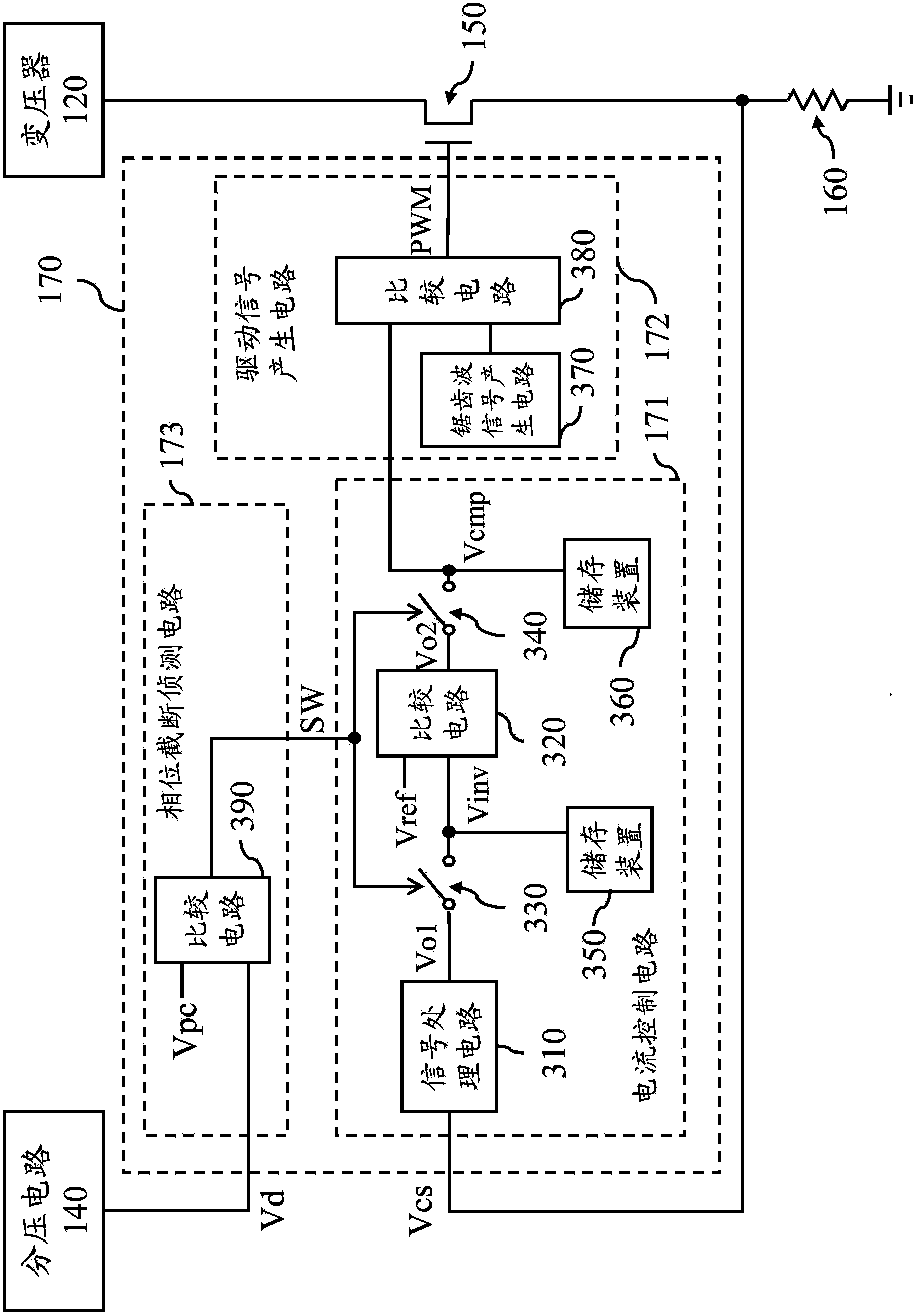
[0023] figure 1 This is a simplified functional block diagram of the dimming system 100 according to an embodiment of the present invention. The dimming system 100 includes a phase cut dimmer 110, a transformer 120, a light-emitting diode group 130, a voltage divider circuit 140, a current switch 150, a resistor 160 and a control device 170. In order to make the drawings more concise and easy to explain, some components, signals, and connections in the dimming system 100 are not shown in figure 1 in. For example, the impedance element of the detailed circuit in the dimming system 100 and the protection circuit of the light-emitting diode group 130 are not shown in figure 1 For ease of explanation.

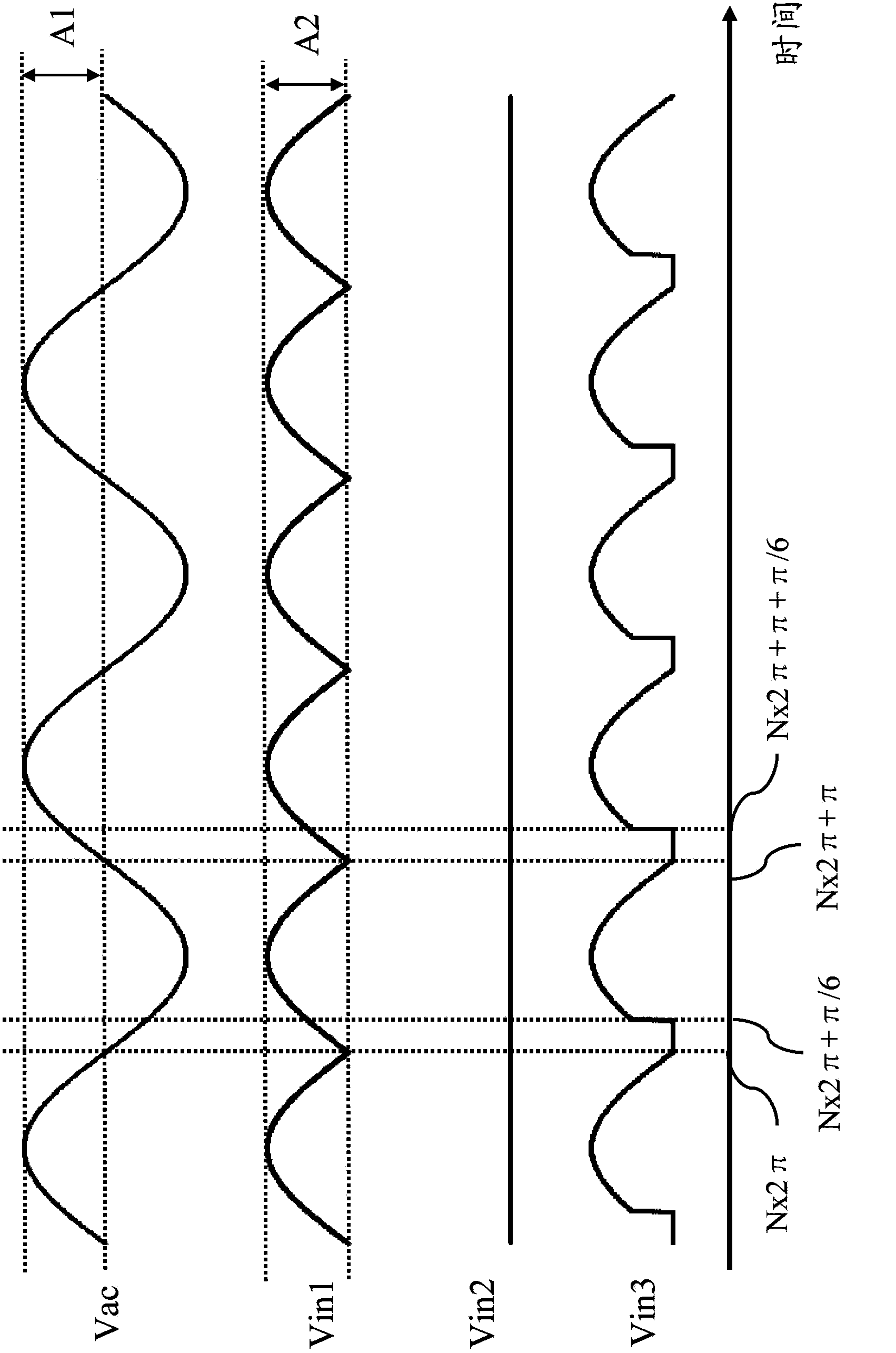
[0024] The phase-cut dimmer 110 is coupled to an AC power sourc...


PUM


Abstract

One light emitting diode control device brought forward by the invention is used for controlling a phase truncation type light modulation system. The phase truncation type light modulation system comprises a light emitting diode and a switch. The light emitting diode control device sets the conduction state of the switch and supplies power to the light emitting diode according to the input signal of phase truncation. The light emitting diode control device can also detect whether the input signal is truncated, when the input signal is truncated, the light emitting diode control device stores the operation parameters of an internal circuit in a storage device, and when the input signal is not truncated anymore, the light emitting diode control device enables the internal circuit to rapidly recover to a previous operation state through the stored operation parameters. In the phase truncation type light modulation system, the light emitting diode control device can reduce the problem that the internal circuit has to be restarted for operation when the input signal is truncated, and by the light emitting diode control device, a proper operation state can be rapidly recovered, the dimming linearity is better, and the light scintillation can also be avoided.

Description

Technical field [0001] The invention relates to a light-emitting diode control device, in particular to a light-emitting diode control device suitable for a phase-cut dimming system. Background technique [0002] Light emitting diodes (LEDs) have high luminous efficiency, long life, small size, fast startup speed, high reliability and are not easily damaged. Therefore, more and more people use light emitting diodes to replace traditional light sources as homes and offices. , Signboards, street lamps and other indoor and outdoor lighting sources. [0003] However, when the light emitting diode is used to replace the traditional light source, it will cause matching problems with the existing lamps. For example, many traditional light sources use phase cut dimming to adjust the brightness of the light source. Phase cut dimmers usually use Triode for Alternating Current (TRIAC) or Elements such as diodes cut off part of the alternating current signal, so that the voltage or current w...

Claims


Application Information

Patent Timeline
Patent Type & Authority Applications(China)
IPC IPC(8): H05B37/02
Inventor 潘均宏唐健夫陈曜洲杨宗熙
Owner RICHTEK TECH
Why Eureka
Try Eureka