
LCD printing equipment

A technology of printing equipment and liquid crystal display, which is applied in the field of equipment in the flat panel display industry, to achieve the effects of preventing damage, improving equipment grafting rate, and improving equipment yield

Active Publication Date: 2016-01-20
NANJING BOE DISPLAY TECH CO LTD
View PDF7 Cites 0 Cited by
  • Summary
  • Abstract
  • Description
  • Claims
  • Application Information

AI Technical Summary

Problems solved by technology

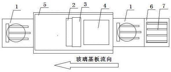
[0026] The present invention aims at the problem that the existing liquid crystal display printing equipment cannot effectively solve the problem of foreign objects on the printing platform, and provides a liquid crystal display printing equipment, which adopts an integrated structure of the workpiece cleaning device and the printing machine, which can effectively solve the foreign objects on the printing platform to improve Equipment production yield; and effectively improve product yield, reduce glass substrate damage rate, reduce the probability of printing plate and A round damage to improve equipment utilization rate

Method used


Image

  • LCD printing equipment
  • LCD printing equipment
  • LCD printing equipment

Examples


Embodiment 1

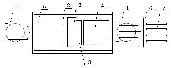
[0051] Such as image 3 As shown, the first arrangement of the workpiece cleaning device of the linear liquid crystal display printing equipment of the present invention includes a robot 1 , a printing machine 5 , a receiving platform 7 and a workpiece cleaning device 8 . The robot 1 is located at the end of the long axis of the printing machine 5, and the receiving platform 7 is located on one side of the robot 1, and the robot 1, the printing machine 5 and the receiving platform 7 are arranged in a straight line.

[0052] The printing machine 5 includes A wheel 2, printing wheel 3, and printing platform 4. The printing wheel 3 can rotate on a fixed axis at the end of the printing platform 4 through the printing wheel control system, and can also roll in a straight line on the printing platform 4; The side above one end of the platform 4 is arranged parallel to the printing wheel 3 .

[0053] Such as Figure 7-10As shown, the workpiece cleaning device 8 includes a main engi...

Embodiment 2

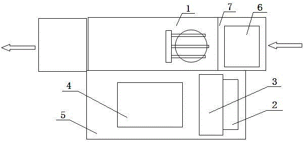
[0056] Such as Figure 4 As shown, the first arrangement of the workpiece cleaning device of the character-shaped liquid crystal display printing equipment of the present invention is different from Embodiment 1 in that the robot 1 is located at the short axis end of the printing machine 5, and the receiving platform 7 is located at the end of the robot 1. On one side, the robot 1, the printing machine 5 and the receiving platform 7 are arranged in an inverted font.

[0057] Operation mode: the workpiece cleaning device 8 in this mode adds a set of walking devices. Before the glass substrate 6 is printed, the workpiece cleaning device 8 is opened and then moves forward on the walking guide rail 13 for cleaning; when there is no glass substrate 6 on the printing platform 4 , the workpiece cleaning device 8 moves forward to clean the printing platform 4 .

Embodiment 3

[0059] Such as Figure 5 As shown, the second arrangement of the workpiece cleaning device of the linear liquid crystal display printing equipment of the present invention is different from the embodiment 1 in that it also includes a walking guide rail 13 . The walking guide rail 13 is arranged on the printing platform 4, parallel to the moving direction of the printing wheel 3; the cleaning head of the workpiece cleaning device of the workpiece cleaning device is arranged on the walking guide rail 13, and an independent driving device is used.

[0060] The mode of operation is the same as that of Example 1.


PUM


Abstract

Liquid crystal display printing equipment comprises a robot, a printing machine, a feed-in platform and an ultrasonic cleaner. The ultrasonic cleaner is arranged on the printing machine, and the ultrasonic cleaner and the printing machine are of an integrated structure. The printing machine comprises a wheel A, a printing wheel and a printing platform. The printing wheel can achieve fixed-axis rotation at the end of the printing platform through a printing wheel control system and can also linearly roll on the printing platform. The wheel A is located above the side portion at one end of the printing platform, and the wheel A and the printing wheel are arranged in parallel. By the adoption of the structure, activation of the liquid crystal display printing equipment is effectively improved, and the printing yield of the liquid crystal display printing equipment is increased.

Description

technical field [0001] The invention relates to equipment in the flat panel display industry, in particular to a liquid crystal display printing equipment. Background technique [0002] A printing machine is a device that prints PI liquid on a printing plate with PI liquid onto a glass substrate. During the printing process, a high-strength extrusion method is used between the glass substrate and the printing plate, so that the PI liquid is printed on the glass substrate. If there is no high-strength extrusion, then the PI liquid will not be able to print on the glass substrate with guaranteed quality. [0003] Traditional printing presses can be mainly divided into two structural modes: [0004] 1. Linear printing machine, such as figure 1 , this linear printing machine drives the glass substrate to move through the movement of the printing platform, so as to achieve the purpose of printing. [0005] Description of working mode of linear printing machine: [0006] ① Th...

Claims


Application Information

Patent Timeline
Patent Type & Authority Patents(China)
IPC IPC(8): B41F35/00
Inventor 何方顾葆华叶宁李广圣赵辉马继然
Owner NANJING BOE DISPLAY TECH CO LTD
Learn More