Shear mode mechanism capable of being controlled in numerical mode and shear mode mechanism drive system formed by shear mode mechanisms in combined mode

A scissor mechanism and numerical control technology, which is applied in the direction of hoisting devices and lifting frames, can solve the problems of small expansion ratio, small load capacity, inaccurate terminal positioning, etc., achieve large expansion ratio, improve load capacity and stability, Accurate effect of telescopic positioning

Inactive Publication Date: 2014-01-22
唐易平
View PDF9 Cites 17 Cited by
  • Summary
  • Abstract
  • Description
  • Claims
  • Application Information

AI Technical Summary

Problems solved by technology

[0003] Existing scissor mechanisms all adopt non-numerical control driving methods, such as air cylinders, oil cylinders or mechanical types, such as U.S. Patent US 8151935B2, US 4867277, etc., these The mechanism has the disadvantage of inaccurate terminal positioning
However, existing numerically controllable mechanisms, such as articulated robotic arms driven by servo motors, have the disadvantages of small expansion ratio and small load capacity.

Method used


Image

  • Shear mode mechanism capable of being controlled in numerical mode and shear mode mechanism drive system formed by shear mode mechanisms in combined mode
  • Shear mode mechanism capable of being controlled in numerical mode and shear mode mechanism drive system formed by shear mode mechanisms in combined mode
  • Shear mode mechanism capable of being controlled in numerical mode and shear mode mechanism drive system formed by shear mode mechanisms in combined mode

Examples


Embodiment Construction

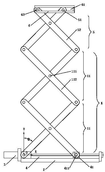
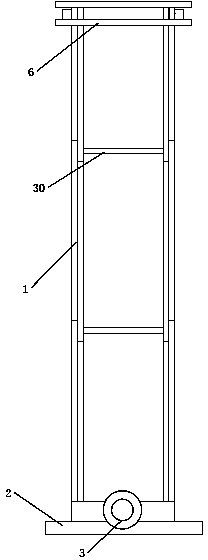
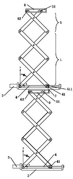
[0019] The present invention is a numerically controllable scissor mechanism, such as figure 1 , 2 As shown, it includes a bracket unit 1, a frame 2, a CNC motor 3 installed on the frame 2, and a ball wire driven by the CNC motor 3, which are hinged at least two pairs of crossed scissor brackets 11 at the ends in turn. Rod 4, one end of the bottom of the pair of scissor brackets 11 at the bottom of the bracket unit 1 is hinged on the base 2 as the origin O, and the other end is hinged on the nut 41 of the ball screw 4; the ball screw 4 and The bracket units 1 are parallel or coincident in a plan view direction. In this embodiment, there are two sets of bracket units, and each of their corresponding hinge points is synchronously connected through the connecting shaft 30, such as figure 1 , 2 As shown, this structure is often applied in the current scissor mechanism. Such as figure 1 As shown, each support unit 1 has two pairs of scissor supports 11 .

[0020] When the CNC...


PUM


Abstract

A shear mode mechanism capable of being controlled in a numerical mode comprises a support unit and further comprises a machine base, a numerical control motor arranged on the machine base, and a ball screw driven by the numerical control motor. End portions of multiple pairs of crossed shear mode supports are sequentially hinged to one another to form the support unit, one of the two ends of the bottoms of the nethermost pair of shear mode supports of the support unit is used as the original point and hinged to the machine base, the other of the two ends of the bottoms of the nethermost pair of shear mode supports of the support unit is hinged to a nut of the ball screw, and therefore the displacement of the shear mode mechanism in the vertical direction can be accurately calculated according to the travel of the numerical control motor, and the aim of controlling the displacement of the shear mode mechanism in the numerical mode is achieved. The shear mode mechanism is accurate in stretching positioning and large in stretching ratio in comparison with a shear mode mechanism, driven by a servo motor, of a joint type mechanical arm. In addition, when the shear mode mechanisms are combined in series or in parallel or in series and in parallel to form a shear mode mechanism drive system, the loading capacity and the stability of the shear mode mechanisms can be greatly improved.

Description

[0001] 【Technical field】 [0002] The invention relates to a numerically controllable scissor mechanism and a combined scissor mechanism driving system, in particular to a composite scissor mechanical arm with accurate positioning, large expansion and contraction ratio and large load. 【Background technique】 [0003] Existing scissor mechanisms all adopt non-numerical control driving methods, such as air cylinder, oil cylinder or mechanical type, such as US patent US 8151935B2, US 4867277, etc. These mechanisms have the disadvantage of inaccurate terminal positioning. However, existing numerically controllable mechanisms, such as articulated manipulators driven by servo motors, have the disadvantages of small expansion ratio and small load capacity. 【Content of invention】 [0004] The purpose of the present invention is to overcome the deficiencies of the prior art and provide a numerically controllable scissor mechanism with accurate positioning, large expansion ratio and ...

Claims


Application Information

Patent Timeline
Patent Type & Authority Applications(China)
IPC IPC(8): B66F7/06B66F7/28
Inventor 唐建柳
Owner 唐易平
Why Eureka
Try Eureka