
A fiber grating demodulator

A technology of fiber grating demodulation and reference grating, which is applied in the direction of transmitting sensing components with optical devices, can solve the problems of different signal sizes, high prices, and unsuitability for practical engineering applications, and achieve self-creep elimination and low cost , the effect of strong practicality and novelty

Active Publication Date: 2016-06-08
浙江振东光电科技有限公司
View PDF4 Cites 0 Cited by
  • Summary
  • Abstract
  • Description
  • Claims
  • Application Information

AI Technical Summary

Problems solved by technology

The traditional method is to use FP etalons with good thermal stability to realize the reference optical path, but FP etalons are expensive and only suitable for laboratory principle verification, not suitable for practical engineering applications
At the same time, in multi-channel applications, because the number and spacing of gratings in each channel are different, the signal size reflected by the gratings is different. How to make the grating signal detection circuit universal and compatible to meet the requirements of different channels is also demodulation The content of the program needs to be studied. At present, there is no good solution from the published prior art.

Method used


Image

  • A fiber grating demodulator
  • A fiber grating demodulator
  • A fiber grating demodulator

Examples


Embodiment Construction

[0022] The present invention will be further described in detail below in conjunction with the accompanying drawings and embodiments.

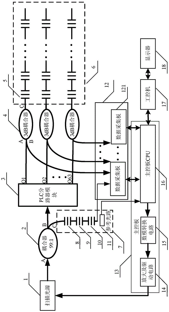
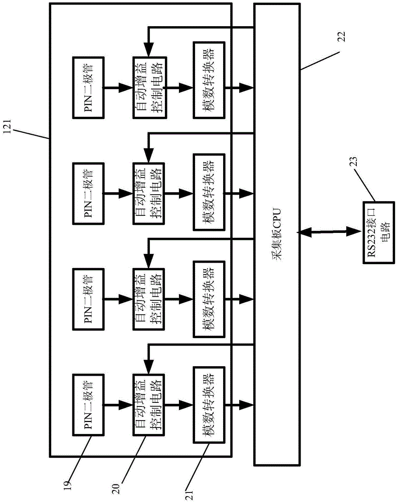
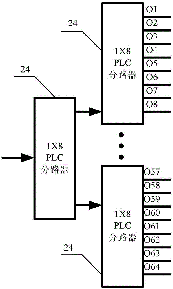
[0023] Such as figure 1The shown fiber grating demodulator includes a scanning light source 1, a coupler 2 with a splitting ratio of 99:1, a PLC splitter module 3, a plurality of 3dB couplers 4, a fiber grating array 6, a reference optical path 7, and a data Acquisition module 12, main control board 13, industrial computer 17 and display 18, wherein the power input end of scanning light source 1 is connected with main control board 13, and scanning light source 1 outputs light signal under the scanning voltage control of main control board 13 output, scanning The optical signal output by the light source 1 enters through the A terminal of the coupler 2, the B terminal of the coupler 2 is the part of the splitting ratio of 99, the C terminal of the coupler 2 is the part of the splitting ratio of 1, and the B terminal of the coupler 2 Connected...


PUM


Abstract

The invention relates to a fiber grating demodulator, which is characterized in that it comprises a scanning light source (1), a coupler (2) with a splitting ratio of 99:1, a PLC splitter module (3), and a plurality of 3dB couplers ( 4), fiber grating array (6), reference optical path (7), data acquisition module (12), main control board (13), industrial computer (17) and display (18), wherein, described reference optical path (7) It includes a first reference grating (8), a second reference grating (9), a third reference grating (10) and a temperature sensor, the temperature sensor is connected to the main control board, the wavelength λ2 of the first reference grating (8) and the second reference grating The wavelength λ3 of the grating (9) is close to one end of the system wavelength, the wavelength λ4 of the third reference grating (10) is close to the other end of the system wavelength, and the ratio of λ4-λ3 to λ3-λ2 is between 4:1 and 7:1 . Compared with the prior art, the present invention uses simple 3 reference gratings and 1 temperature sensor to replace the expensive FP etalon as the reference optical path, which effectively eliminates the creep, hysteresis and drift of the scanning light source. The impact of changes in the output wavelength of the light source on the precision and accuracy of demodulation.

Description

technical field [0001] The invention relates to a fiber grating demodulator. Background technique [0002] In recent years, temperature and pressure sensor measurement systems based on fiber gratings have been widely used in the fields of electric energy, petrochemical industry, rail transit, tunnels and bridges, and become a bright spot of economic growth. Related technologies have also become a hot research topic. Fiber Bragg grating measurement technology can realize long-distance real-time measurement and monitoring, and has the characteristics of wide measurement range, high precision and high stability, especially in strong electromagnetic interference occasions or explosion-proof occasions. [0003] Traditionally, fiber grating demodulation technology uses spectrometers, color filters and wavelength meters, but these demodulation systems have disadvantages such as high price and large volume, which are not suitable for engineering applications. For this reason, many ...

Claims


Application Information

Patent Timeline
Patent Type & Authority Patents(China)
IPC IPC(8): G01D5/26
Inventor 王杨峰夏旭鹏韦冬青潘建懿陈绪英
Owner 浙江振东光电科技有限公司
Learn More