Film type resistance strain gauge used in high-pressure hydrogen sulfide environment

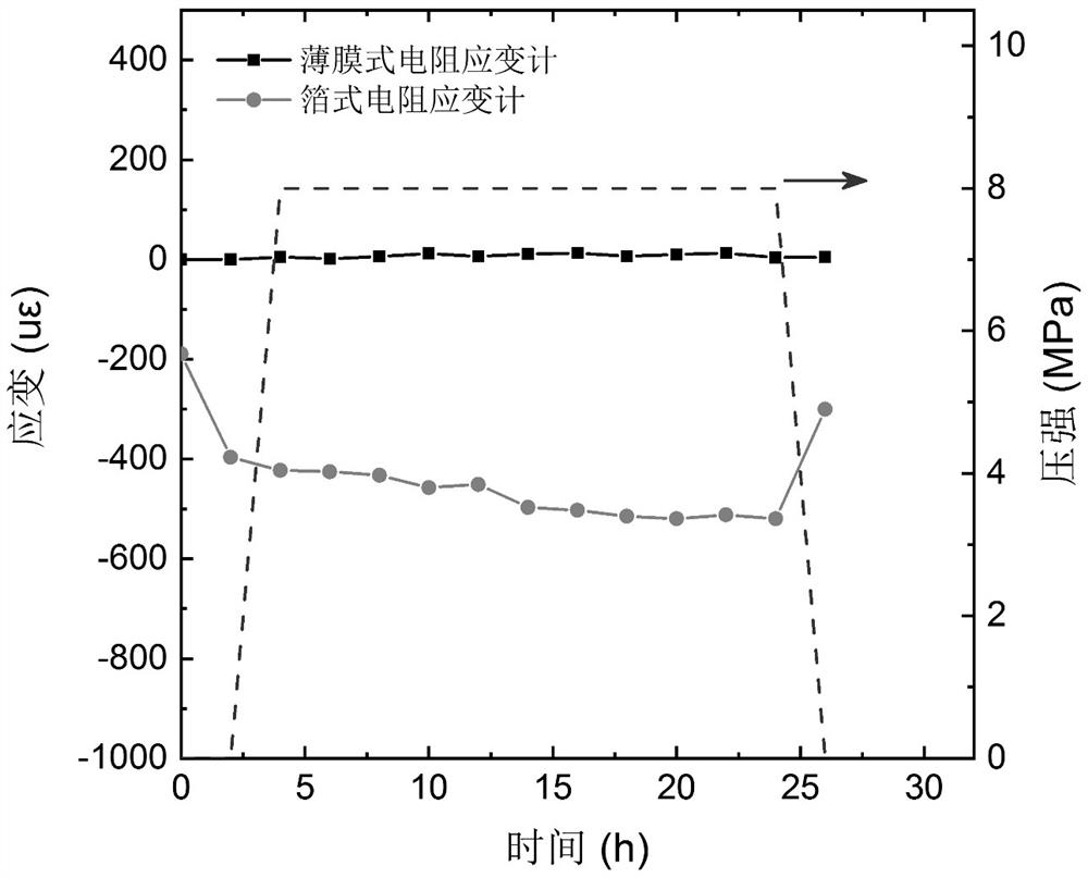
A resistance strain gauge, thin-film technology, applied in the field of sensors, can solve problems affecting measurement accuracy and stability, strain gauge hysteresis and creep, adhesive failure, etc., to avoid strain transmission errors and pressure effects, and eliminate zero drift and creep, to achieve the effect of temperature self-compensation

Pending Publication Date: 2021-03-19
ZHEJIANG UNIV OF TECH
View PDF0 Cites 0 Cited by
  • Summary
  • Abstract
  • Description
  • Claims
  • Application Information

AI Technical Summary

Problems solved by technology

However, the resistance of ordinary foil resistance strain gauges will change with the infiltration of hydrogen atoms, which will cause the zero point drift and creep phenomenon of the strain gauge to aggravate with the increase of time and pressure, seriously affecting the accuracy and stability of the measurement
[0004] At present, the load sensors under high-pressure hydrogen sulfide environment have been developed in my country. The installation of resistance strain gauges is usually pasted with organic adhesives. However, these adhesive materials have a series of problems in high-pressure hydrogen sulfide environments, which greatly limit the service life of strain gauges.
In particular, when the adhesive is in contact with hydrogen sulfide, hydrogen atoms will enter the adhesive through adsorption, intrusion, dissolution and diffusion, causing hydrogen absorption and expansion to occur, resulting in the failure of the adhesive
In addition, since the adhesive is not a sensing element and is sensitive to environmental conditions and will change under the influence of time, temperature and pressure, it is often the main factor causing errors such as hysteresis and creep of the strain gauge, zero point drift, etc.
Adhesives commonly used in current tests are not suitable for test applications, so it is necessary to develop a stable and accurate resistance strain gauge in a high-pressure hydrogen sulfide environment

Method used


Image

  • Film type resistance strain gauge used in high-pressure hydrogen sulfide environment
  • Film type resistance strain gauge used in high-pressure hydrogen sulfide environment
  • Film type resistance strain gauge used in high-pressure hydrogen sulfide environment

Examples


Embodiment 1

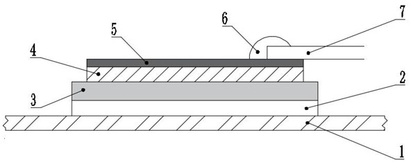
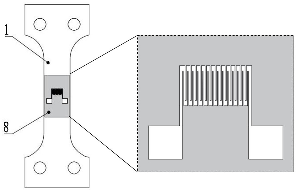
[0041] Such as figure 1 , figure 2 As shown, a thin-film resistance strain gauge used in a high-pressure hydrogen sulfide environment includes a substrate 1, a transition buffer layer 2 arranged on the upper surface of the substrate, an insulating layer 3 arranged on the upper surface of the transition buffer layer, and a The functional layer 4 on the upper surface of the insulating layer, the protective layer 5 on the upper surface of the functional layer; the base is made of 316L stainless steel, the transition buffer layer is Cr film, and the insulating layer is AlN film. The functional layer is a FeNi alloy film. Two lead wires 7 are connected to the protective layer 5 through solder 6;

[0042] A preparation method of a thin-film resistance strain gauge, comprising the steps of:

[0043] (3-1) Place the pretreated substrate in the sputtering chamber of the magnetron sputtering apparatus for fixing and finishing;

[0044] The upper surface of the substrate is polished...

Embodiment 2

[0065] The difference between this embodiment and embodiment 1 is:

[0066] The Cr film is used as a transitional buffer layer with a thickness of 300nm.

[0067] Vacuum the sputtering chamber to 5.0×10 -4 Pa, the substrate temperature of the sample turret is raised to 100°C by heating the substrate to transfer heat, adjust the bias voltage to 80V, feed argon into the sputtering chamber, control the argon flow rate to 25 sccm, and raise the air pressure in the sputtering chamber to 1.8Pa, raise the voltage of A target seat to 350V for glow discharge, ionize the argon gas, generate argon gas ions, and argon gas ions bombard the Cr target material, causing sputtering of the target material; adjust the working pressure in the sputtering chamber to 0.15Pa , carry out pre-sputtering for 10 min; after the pre-sputtering process, after the voltage and current of A target base are stabilized, control the rotation speed of the sample turntable at 2r / min, adjust the voltage and current...

Embodiment 3

[0070] The difference between this embodiment and embodiment 1 is:

[0071] Sputtering an AlN film on the upper surface of the Cr film with a thickness of 400nm as an AlN insulating layer;

[0072]Adjust the temperature controller of the sputtering instrument so that the substrate temperature of the sample turntable rises to 300°C, and the flow rate of nitrogen gas is 25 sccm, so that Ar:N 2 1:1.2, the air pressure in the sputtering chamber is 0.5Pa during the sputtering process, the power of the C target seat is 150W during the sputtering process, and the continuous sputtering is 120min, forming an AlN film on the surface of the sputtered Cr film;

[0073] sputtering grid-shaped FeNi film on the mask with a thickness of 1000nm as a functional layer;

[0074] The sputtering parameters in the process of sputtering FeNi film are: vacuumize the sputtering chamber to 1.0×10 -4 Pa, the substrate temperature is heated to 200°C, the flow rate of argon gas is 22sccm, the air pressur...


PUM

PropertyMeasurementUnit
thicknessaaaaaaaaaa
sizeaaaaaaaaaa
thicknessaaaaaaaaaa

Abstract

The invention discloses a film type resistance strain gauge used in a high-pressure hydrogen sulfide environment. The film type resistance strain gauge comprises a substrate, a transition buffer layerarranged on the upper surface of the substrate, an insulating layer arranged on the upper surface of the transition buffer layer, a functional layer arranged on the upper surface of the insulating layer, and a protective layer arranged on the upper surface of the functional layer, wherein the substrate is made of a 316L stainless steel material, the transition buffer layer is a Cr film, the insulating layer is an AlN film, the functional layer is a FeNi alloy film, and the protective layer is a CrOx film. In a high-pressure hydrogen sulfide environment, the film type resistance strain gauge can be firmly fixed on a test sample, and the connection between the film type resistance strain gauge and the test sample is inorganic so that zero drift and creep deformation are eliminated, temperature self-compensation is realized, and the sensitivity of the film type resistance strain gauge and the accuracy of a measurement result are improved.

Description

technical field [0001] The invention relates to the technical field of sensors in a high-pressure hydrogen sulfide environment, in particular to a sensor made of Cr film, AlN film, FeNi film and CrO x A thin-film resistance strain gauge for high-pressure hydrogen sulfide environments composed of membranes. Background technique [0002] Hydrogen energy is regarded as the clean energy with the most development potential in the 21st century, and it is an ideal energy carrier. At present, there are four main methods of hydrogen production: hydrogen production from fossil fuels, hydrogen production from industrial by-products, hydrogen production from electrolysis of water, biomass and other hydrogen production methods. Among them, from the perspective of cost, the economy of hydrogen production from natural gas is the most significant. my country's natural gas resources are mainly natural gas resources with high hydrogen sulfide content, and the gas fields are mainly distribut...

Claims


Application Information

Patent Timeline
Patent Type & Authority Applications(China)
IPC IPC(8): G01B7/16G01L1/22C22C38/08C23C14/04C23C14/06C23C14/08C23C14/16C23C14/35C23C14/58
CPCC22C38/08C23C14/0036C23C14/042C23C14/0617C23C14/083C23C14/165C23C14/35C23C14/5806G01B7/18G01L1/2287
Inventor 刘哲晔张林张雯丽张万亮
Owner ZHEJIANG UNIV OF TECH
Why Eureka
Try Eureka