
Force and pressure measurement model of bridge

A force measurement and pressure measurement technology, which is applied in the direction of measuring devices, aerodynamic tests, and machine/structural component testing, can solve problems such as inaccurate force measurement, mutual interference of forces, and large errors in pressure integration methods, so as to avoid End effect, the effect of improving accuracy

Active Publication Date: 2014-01-22
HUNAN UNIV
View PDF6 Cites 11 Cited by
  • Summary
  • Abstract
  • Description
  • Claims
  • Application Information

AI Technical Summary

Problems solved by technology

Facts have proved that the pressure integration method assumes that a pressure measuring hole represents the pressure of a small area around it, which is different from the actual pressure distribution, so the result has a certain error, and for the section with more edges and corners on the surface, because it is impossible to lay pipes, the pressure The integral method has a larger error
At present, although the aerodynamic force can be measured through the high-frequency force measuring balance connected to both ends of the segment model, the forces in the three directions will interfere with each other, resulting in inaccurate force measurement

Method used


Image

  • Force and pressure measurement model of bridge
  • Force and pressure measurement model of bridge
  • Force and pressure measurement model of bridge

Examples


Embodiment Construction

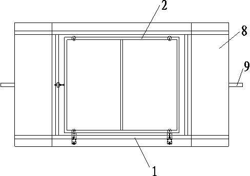
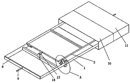
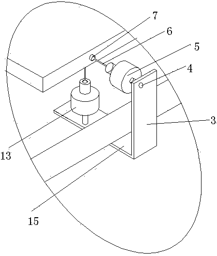
[0020] Such as figure 1 As shown, a bridge force measurement and pressure measurement model includes a rectangular suspension frame 2, a suspension frame coat 10 outside the suspension frame 2, a force measuring mechanism for measuring the force of the suspension frame 2, and a rectangular support set under the suspension frame 2. Frame 1, the length of the long side of the support frame 1 is greater than the length of the long side of the suspension frame 2, and the length of the wide side of the support frame 1 is greater than the length of the wide side of the suspension frame 2; The axial force sensor 12 with the central line of the wide side of the frame 2 on a straight line, a plurality of vertical force sensors 13 vertically arranged at the bottom of the suspension frame 2, and a plurality of vertical force sensors 13 arranged on one side of the suspension frame 2 and parallel to the direction of the width of the suspension frame 2 A plurality of lateral force sensor...


PUM


Abstract

The invention relates to a force and pressure measurement model of a bridge. The model comprises a rectangular suspension frame, a suspension frame cover outside the suspension frame and a force measurement mechanism for measuring force of the suspension frame, wherein the force measurement mechanism comprises an axial force sensor, a plurality of vertical force sensors and a plurality of lateral force sensors, the axial force sensor is arranged at the end part of the suspension frame and located in the same straight line with a center line of the wide side of the suspension frame, the vertical force sensors are vertically arranged at the bottom of the suspension frame, and the lateral force sensors are arranged on one or two side surfaces of the suspension frame and parallel to the wide side direction of the suspension frame. According to the force and pressure measurement model of the bridge, the force sensors are distributed in multiple directions, so that force in all directions can be measured; disturbance elimination components are arranged between each force sensor and the suspension frame, so that the force in all directions can be transmitted to corresponding force sensors as much as possible, the accuracy of measured force is greatly improved, and aerodynamic force of the bridge model is obtained accurately; and rectangular end blocks arranged at two ends of the suspension frame are taken as compensation sections, accordingly, the end effect can be avoided, and a flow field of a suspension section can be close to a two-dimensional flow as much as possible.

Description

technical field [0001] The invention relates to a bridge force measurement and pressure measurement model, which is suitable for testing the aerodynamic force of a section model in a wind tunnel. Background technique [0002] Bridges are often located on open rivers, seas or canyons, where the wind speed is relatively high, and the effect of wind on bridges cannot be ignored. With the development of bridge-building technology, the trend of bridges developing towards long-span and softness becomes more and more obvious, and wind load becomes the control load of bridge design. How to prevent the occurrence of wind-damaged accidents of bridges has become an important issue in the field of wind engineering. [0003] The influence of wind on bridges is mainly manifested as wind-induced vibration, and the forms of wind-induced vibration of bridges include eddy vibration, flutter, buffeting and galloping. To study these vibration forms, one of the most important tasks is to obtai...

Claims


Application Information

Patent Timeline
Patent Type & Authority Applications(China)
IPC IPC(8): G01M9/08G01M9/06
Inventor 牛华伟陈谨林陈政清
Owner HUNAN UNIV
Learn More