Pneumatic tire

A technology for pneumatic tires and carcass, applied to the reinforcement layer of pneumatic tires, special tires, tire parts, etc., which can solve the problems of reduced handling stability, reduced tire lateral rigidity, and reduced lateral rigidity. Effects of reduced air resistance, reduced tire mass, and reduced energy loss

Inactive Publication Date: 2016-06-15
SUMITOMO RUBBER IND LTD
View PDF7 Cites 4 Cited by
  • Summary
  • Abstract
  • Description
  • Claims
  • Application Information

AI Technical Summary

Problems solved by technology

Therefore, the lateral rigidity of the tire is also reduced, and there is a new problem that should be solved in that the lateral rigidity is reduced and the steering stability is reduced.

Method used


Image

  • Pneumatic tire
  • Pneumatic tire
  • Pneumatic tire

Examples


Embodiment

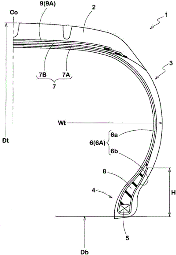
[0061] (1) has such as figure 1 Pneumatic tires with the internal configuration shown in Table 1 were manufactured, and then each test tire was tested for rolling resistance, air resistance, ride comfort, handling stability, and road noise.

[0062] Its general specifications are as follows:

[0063] Carcass:

[0064] Number of curtains: 1 piece

[0065] Cord angle: 90 degrees

[0066] Belt:

[0067] Number of curtains: 2 pieces

[0068] Cord angle: 22 degrees, -20 degrees

[0069] Cord: Steel

[0070] Belt layer:

[0071] Number of curtains: 1 piece

[0072] Cord angle: about 0 degrees

[0073] Cord: Nylon

[0074] rolling resistance:

[0075] Using a rolling resistance tester, the rolling resistance (unit: N) of the tire was measured under the following conditions. In the evaluation, the reciprocal of the measured value was expressed as an index, and the value of Comparative Example 1 was set as 100. The larger the value, the lower the rolling resistance.

[00...


PUM


Abstract

In order to improve fuel economy while ensuring driving stability, a pneumatic tire is provided with one carcass ply, two belt plies, and one band ply, and satisfies the following: Wt <= -0.7257*(Db)<2> + 42.763*Db - 339.67 ---(1); Wt >= -0.7257*(Db)<2>+ 48.568*Db - 552.33 ---(2); Dt <= 59.078 Wt<0.498> ---(3); Dt >= 59.078*Wt<0.467> ---(4), where Wt (unit: mm) is the tire cross section width, Db (unit: inches) is the bead diameter, and Dt (unit: mm) is the tire outer diameter, with a carcass cord being made of an aramid fiber cord.

Description

technical field [0001] The present invention relates to a pneumatic tire capable of ensuring steering stability while improving fuel consumption. Background technique [0002] The main factors related to tire fuel consumption are rolling resistance and air resistance of the tire. The main cause of tire rolling resistance is energy loss due to repeated deformation of the rubber while driving. In order to reduce this rolling resistance, the use of tread compounds with low energy loss (low tan δ) is advocated. [0003] When a tread compound having low energy loss is used, although rolling resistance is reduced, grip performance (especially wet grip performance) is lowered, and there is also a problem that wear resistance deteriorates. As shown in Patent Documents 1 and 2 below, studies have been conducted on tread rubber compositions having reduced rolling resistance while improving wear resistance. However, relying only on the improvement of the rubber composition cannot pr...

Claims


Application Information

Patent Timeline
Patent Type & Authority Applications(China)
IPC IPC(8): B60C9/08B60C9/00D07B1/02D07B1/06
CPCD02G3/48D10B2331/021B60C3/04B60C2015/009B60C2009/0475B60C2009/0466B60C9/2204B60C9/0042B60C9/08B60C9/18B60C11/00B60C13/00B60C15/0009B60C15/04B60C2009/0035B60C2009/0092
Inventor 梶田弘明
Owner SUMITOMO RUBBER IND LTD
Why Eureka
Try Eureka