Al technical title is built by PatSnap Al team. It summarizes the technical point description of the patent document.
A crack inspection, saggar technology, applied in the direction of optical testing flaws/defects, etc., can solve the problems of energy waste, difficult to obtain cleaning effect, low inspection efficiency, etc.
Active Publication Date: 2015-09-23
SUZHOU HUIKE EQUIP CO LTD
View PDF4 Cites 3 Cited by
Summary
Abstract
Description
Claims
Application Information
AI Technical Summary
This helps you quickly interpret patents by identifying the three key elements:
Problems solved by technology
Method used
Benefits of technology
Problems solved by technology
Furthermore, as known in the industry, since the sagger is frequently affected by the alternation of sudden heat and sudden cold, as time goes by and / or the number of times of repeated use increases, tiny cracks will appear in the sagger and the tiny cracks will gradually expand until the sagger is used. The whole sagger is broken
Therefore, if the saggers with fine cracks cannot be detected and removed in advance, once they burst (crack) during firing in the kiln, the following technical problems will occur: First, the broken saggars will affect the quality of the saggers. The normal operation of the conveying roller, and it will also stay in the furnace of the electronic kiln, thus causing the operation failure of the electronic kiln; the second is that the electronic powder material previously installed in the sagger cannot be drawn out of the furnace due to the broken sagger. On the one hand, it causes waste, on the other hand, it also causes the operation failure of the electronic kiln; the third is that it is troublesome to remove the electronic powder material deposited in the furnace due to the fragmentation of the sagger, so the work intensity of the workers for cleaning the furnace is high and it is difficult to obtain expectations. Fourth, when removing the electronic powder materials left by the broken sagger in the furnace, it is usually necessary to wait for the electronic kiln to stop working and after the furnace temperature drops to normal temperature, it will seriously Affect the firing efficiency of electronic kilns and cause energy waste
[0003] In order to avoid the above-mentioned problems as much as possible, the prior art usually checks the saggers manually, and one of the shortcomings of manual inspection is that the inspection efficiency is low; two, because the tiny cracks are usually difficult to be found by the inspector's naked eyes; three, because Manual inspection (combination of visual observation and tap listening) is easily constrained by differences in worker experience, job responsibilities, and even emotional changes, so it is difficult to fully guarantee the detection effect of saggers
Method used
Image
Click on the blue label to locate the original text in one second.
Reading with bidirectional positioning of images and text.
Examples
Embodiment Construction
[0019] In order to enable the examiners of the patent office, especially the public, to more clearly understand the technical essence and beneficial effects of the present invention, the applicant will describe in detail below by way of examples, but the descriptions of the examples are not intended to describe the solution of the present invention. Restriction, any equivalent transformation made according to the concept of the present invention is only formal but not substantive, and should be regarded as the scope of the technical solution of the present invention.
[0020] In the following description, all concepts related to the orientation of up, down, left, right, front and rear are for the position state shown in the figure, so it should not be construed as a specific limitation to the solution of the present invention.
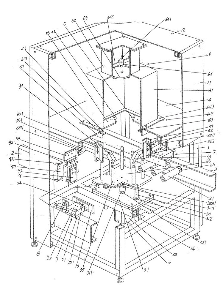
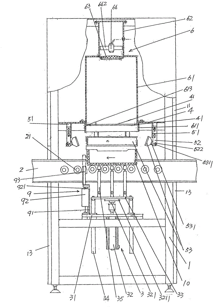
[0021] See figure 1 , a rack 1 is given, a side shading plate 11 is arranged on the upper part of the rack 1 and around the perimeter of the rack 1, a...
PUM
Abstract
The invention relates to a crack inspection device for a sagger, and belongs to the technical field of detection of ceramic vessels. The device comprises a frame, a sagger lifting mechanism, a baffle, a group of light source mechanisms, an optical signal response mechanism, a pair of sagger clamping mechanisms, a sagger position signal collector, and a temporary sagger positioning mechanism, wherein the frame is matched with a pair of sagger conveying roller pivoting bearing beams of an automatic production line of an electronic kiln, the sagger lifting mechanism is arranged on the lower part of the frame, the baffle is fixedly arranged on the upper part of the frame and a magazine matching connector is arranged in the central position of the baffle, the group of light source mechanisms are fixed together with one side, facing the sagger lifting mechanism, of the baffle, the optical signal response mechanism is fixed together with one side, backing the optical signal response mechanism, of the baffle, the pair of sagger clamping mechanisms are arranged on the pair of sagger conveying roller pivoting bearing beams, the sagger position signal collector is arranged on one of the sagger conveying roller pivoting bearing beams, and the temporary sagger positioning mechanism is arranged on the lower part of the frame. A group of side shielding plates are arranged on the upper part of the frame, a shielding plate is fixedly arranged at the top of the frame, and the optical signal response mechanism is surrounded by the side shielding plates, the top shielding plate and the baffle. The device can be used for automatically detecting flawed saggers and avoiding influence of fragmentation on normal operation of the electronic kiln.
Description
technical field [0001] The invention belongs to the technical field of auxiliary facilities for electronic kilns, and in particular relates to a saggar crack inspection device, which is matched with an automatic production line of electronic kilns and checks whether there are cracks in a saggar used for containing electronic powder materials. Background technique [0002] As is known in the industry, when the electronic kiln sinters the electronic powder material (also called sintering), the electronic powder material (raw meal) needs to be loaded into the sagger, and the saggar and the electronic powder material enter the electronic kiln for firing After firing, the electronic powder material (clinker) is carried out of the kiln by the saggar, and the electronic powder material in the saggar is crushed at the crushing station, and then the saggar is poured out to remove the electronic powder The empty saggar behind the body material is cleaned by the cleaning station and th...
Claims
Application Information
Patent Timeline
Application Date:The date an application was filed.
Publication Date:The date a patent or application was officially published.
First Publication Date:The earliest publication date of a patent with the same application number.
Issue Date:Publication date of the patent grant document.
PCT Entry Date:The Entry date of PCT National Phase.
Estimated Expiry Date:The statutory expiry date of a patent right according to the Patent Law, and it is the longest term of protection that the patent right can achieve without the termination of the patent right due to other reasons(Term extension factor has been taken into account ).
Invalid Date:Actual expiry date is based on effective date or publication date of legal transaction data of invalid patent.