Device for the inductive transmission of electric energy

An inductive and equipment technology, applied in circuits, charging stations, inductors, etc., can solve the problems of high cost of the primary coil and secondary coil structure, and achieve the effects of good user friendliness, increased power, and increased tolerance

Active Publication Date: 2014-01-22
AUDI AG
View PDF6 Cites 12 Cited by
  • Summary
  • Abstract
  • Description
  • Claims
  • Application Information

AI Technical Summary

Problems solved by technology

But the construction costs for a large number of

Method used


Image

  • Device for the inductive transmission of electric energy
  • Device for the inductive transmission of electric energy
  • Device for the inductive transmission of electric energy

Examples


Example Embodiment

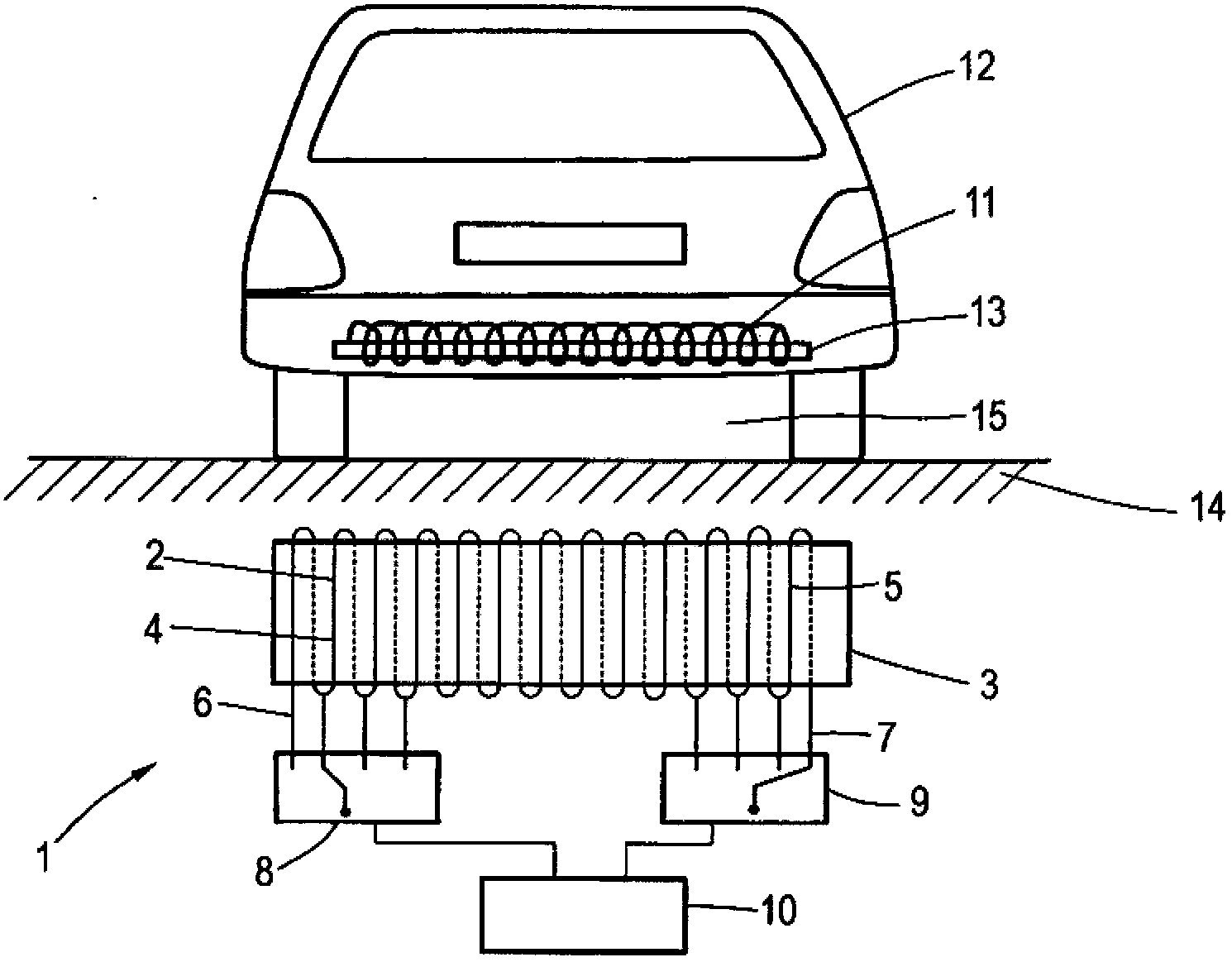
[0023] exist figure 1 The device 1 for inductively transmitting electrical energy shown in , comprises a primary coil 2 which is wound around a pure iron body / ferrite 3 arranged horizontally in the assembled state as a coil core. The primary coil 2 has opposite end sections 4 , 5 and extends from the end section 4 to the opposite end section 5 .

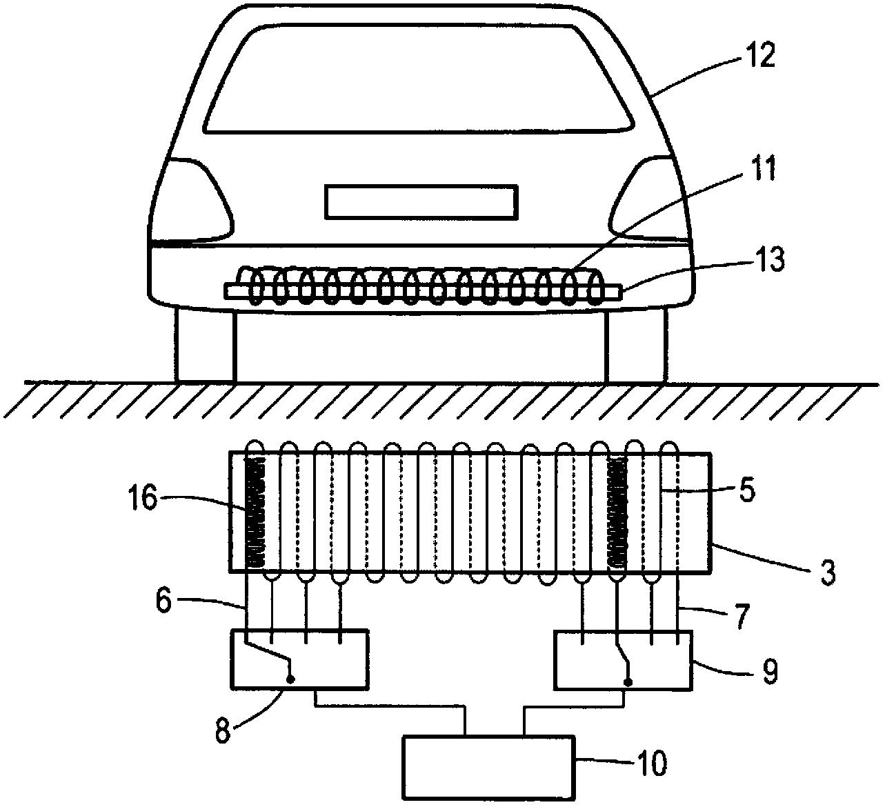
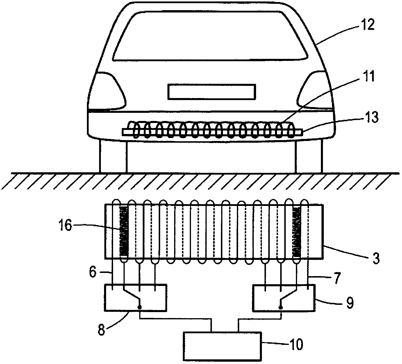
[0024] exist figure 1 It can be seen that the primary coil 2 has a plurality of coil leads 6, 7, wherein the coil lead 6 is assigned to the figure 1 in the end section 4 on the left, while the coil terminal 7 is assigned to the figure 1 The end section 5 shown on the right. The coil terminals 6 , 7 are connected to a multi-stage switch 8 , 9 respectively, and the two switches 8 , 9 are connected to a control device 10 . The control device 10 actuates the two switches 8 , 9 , so that in each case a specific part of the end sections 4 , 5 of the primary coil 2 is connected or switched on. exist figure 1 It can be seen from the di...


PUM


Abstract

The present invention relates to a method for the electric power from the stationary unit disposed inside the primary coil (2) to the inductive transmission provided in the vehicle (12) inside the secondary coil (11) of the device, wherein the primary coil (2) and / or the secondary coil (11) having at least one lead-off coil head (6, 7) for adjusting the effective length of the coil for inductive transmission of energy.

Description

technical field [0001] The invention relates to a device for inductively transferring electrical energy from a primary coil arranged in a stationary unit to a secondary coil arranged in a vehicle. Background technique [0002] Electric vehicles require charging devices for recharging the electric energy storage at regular intervals. Charging devices in which the user initiates the charging process by connecting the charging cable to a socket installed in the vehicle are not popular due to their lack of user friendliness. Instead, the trend in electric vehicles is charging devices based on contactless energy transfer. [0003] Typically at least one primary coil generates a magnetic field capable of transferring energy across the air gap to the secondary coil. But efficient and reliable energy transfer across the air gap requires good positioning of the primary and secondary coils, so optimally, the vehicle is parked over the (charging) device such that the secondary coil i...

Claims


Application Information

Patent Timeline
IPC IPC(8): H02J17/00H02J7/00B60L11/18H01F38/14
CPCH01F38/14Y02T90/12Y02T90/14Y02T10/7072B60L53/39B60L53/126Y02T10/70H02J50/90H02J50/10B60L53/12
Inventor B·埃利亚斯R·佩尔
Owner AUDI AG
Why Eureka
Try Eureka