A machine for cutting leathers
What is Al technical title?
Al technical title is built by PatSnap Al team. It summarizes the technical point description of the patent document.
A cutting machine, leather technology, applied in leather punching/punching/cutting, small raw hide/large raw hide/leather/fur mechanical processing, raw hide/leather/fur manufacturing equipment, etc., can solve high labor costs, limit leather Cutting machine productivity and other issues to achieve the effect of reducing time
Active Publication Date: 2014-01-22
TESEO SPA
View PDF6 Cites 12 Cited by
Summary
Abstract
Description
Claims
Application Information
AI Technical Summary
This helps you quickly interpret patents by identifying the three key elements:
Problems solved by technology
Method used
Benefits of technology
Problems solved by technology
In other words, the time to collect the cut pieces constitutes the "bottleneck" of each working cycle, which greatly limits the productivity of the leather cutting machine
[0015] Another drawback is that the collection and sorting operations of the cut pieces, although not requiring special skills, are carried out by the same operators with special skills who are responsible for placing the hides: this therefore means higher labor costs, which This higher labor cost is not in any case indispensable to accomplish the above operations
Method used
Image
Click on the blue label to locate the original text in one second.
Reading with bidirectional positioning of images and text.
Examples
Embodiment Construction
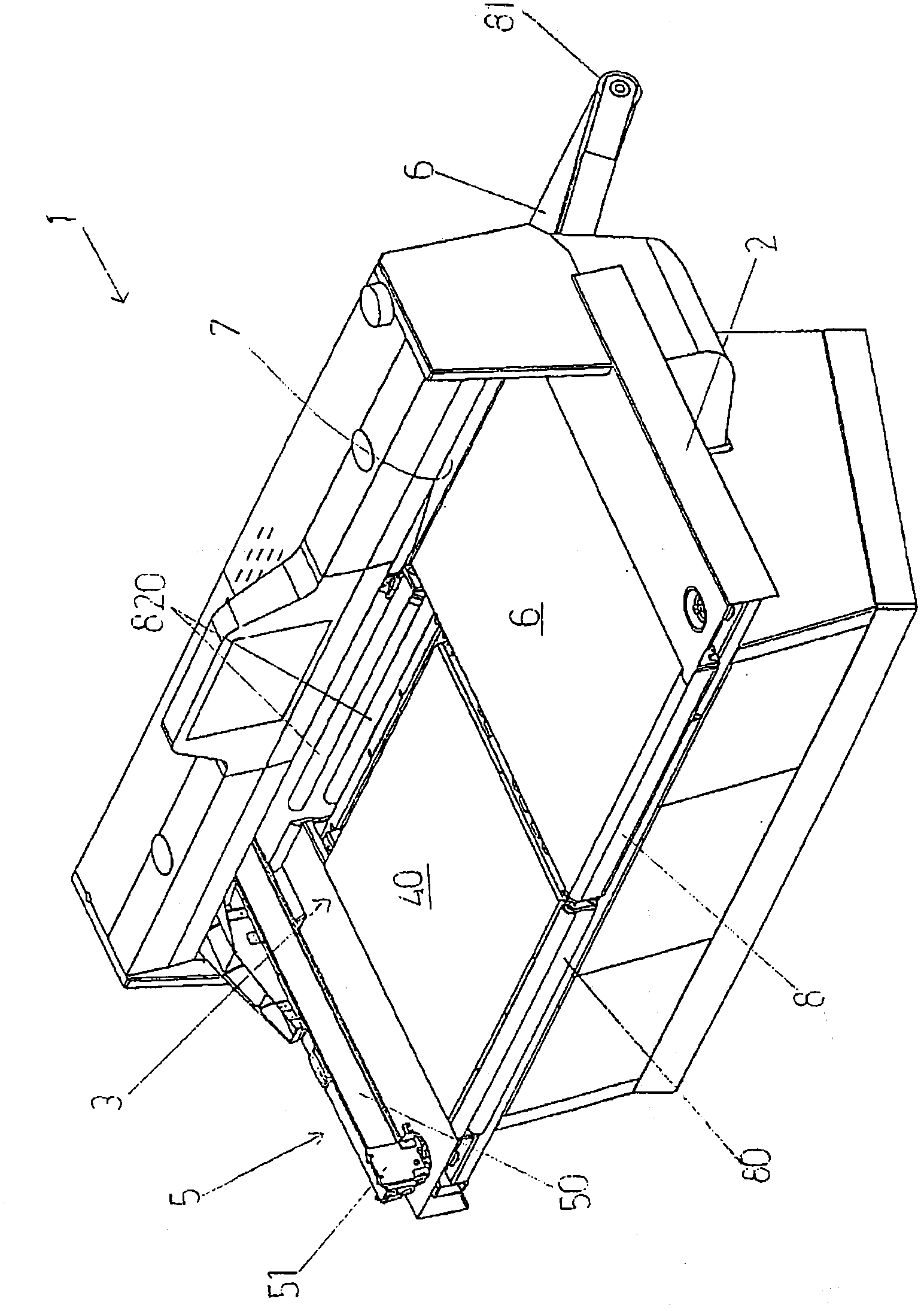
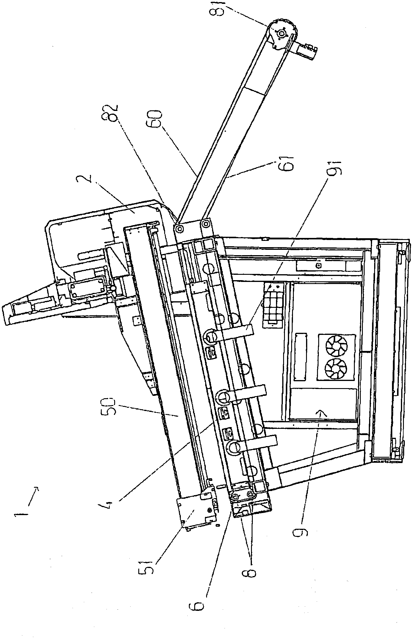
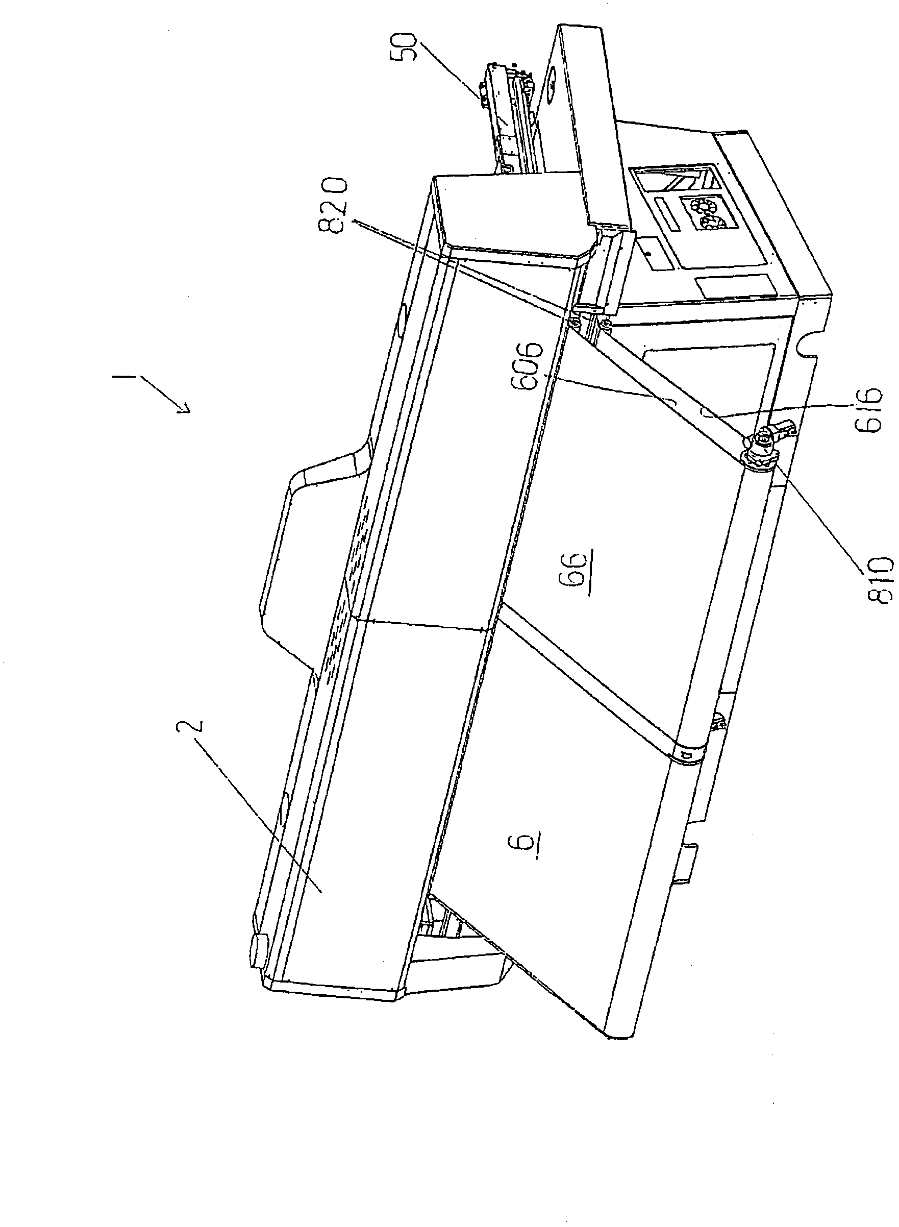
[0024] With reference to the attached figures, 1 generally indicates a leather cutting machine according to the invention.
[0025] The leather cutting machine 1 comprises: a structure 2 defining an operating area 3 in which the hides are to be placed and kept unfolded and stationary in order to allow the cutting operation; at least one suction plane 4, 40, It is arranged at the operating area 3 and is connected to a low pressure source 9 in order to keep the leather unrolled and stationary after activation of said low pressure source 9 .
[0026] The leather cutting machine 1 further comprises: a cutting unit 5, carried by the structure 2, arranged above the operation area 3 and movable relative to the operation area 3, so as to cut the Leather (ie the cut area of the leather completely coincides with the unfolded area of the leather).
[0027] The leather cutter 1 further comprises at least two closure strips 6, 66 made of permeable material and their sides abutting eac...
PUM
Abstract
A machine for cutting leathers (1), comprising: a structure (2) which circumscribes an operating area (3) where the leathers are to be laid, maintained stretched and still such as to allow cutting operations; at least an aspirating plane (4, 40) arranged at the operating area (3) and connected to a depression source (9) such as to maintain the leather stretched and still following activation of the depression source (9); a cutting unit (5), borne by the structure (2), arranged above the operating area (3) and movable with respect thereto, such as to realise the cut In the leathers in the operating area (3); the machine (1) comprising at least two closed-loop belts (6, 66) made of a permeable material and flanked to one another, each comprising an upper branch (60, 606) and a lower branch (61, 616), each of the belts (6, 68) being arranged such that the upper branch (60, 606) thereof remains above and in proximity of the aspirating plane (4, 40), in order to restingly receive the leathers to be cut and in order to enable laying of the leathers thereon; the belts (6, 66) being attracted by the aspirating plane (4, 40) following activation of the depression source (9), such that the leathers thereon remain stretched and still; the structure (2) comprising an outlet passage (7) of the leathers, arranged facing the upper branch (60, 606) of each of the belts (6, 66); each belt (6, 66) being activatable, following the completion of the cutting operations thereon, such that the relative upper branch (60, 606) is movable towards the outlet passage (7) in order for the cut leathers to be transferred out of the operating area (3), externally of the structure (2), independently of the other belt (6, 66).
Description
technical field [0001] The present invention relates to the technical field of processing leather or the like, in particular, the present invention relates to a leather cutting machine. Background technique [0002] In the aforementioned technical fields, it is a well-known requirement to keep the hide fully unfolded during the cutting operation, in order to prevent possible creasing or wrinkling from altering the final desired shape of the hide obtained. [0003] For this purpose, the known hide cutting machines comprise a structure which encloses an operating area in which the hide must be unrolled and kept unrolled and stationary before the hide is subjected to the cutting operation. [0004] Said leather cutting machine comprises, at the relevant operating area, a fixed suction plane made of steel and arranged horizontally, said suction plane providing a plurality of through holes, [0005] The through hole is connected to a low pressure source, ie for example a suction...
Claims
Application Information
Patent Timeline
Application Date:The date an application was filed.
Publication Date:The date a patent or application was officially published.
First Publication Date:The earliest publication date of a patent with the same application number.
Issue Date:Publication date of the patent grant document.
PCT Entry Date:The Entry date of PCT National Phase.
Estimated Expiry Date:The statutory expiry date of a patent right according to the Patent Law, and it is the longest term of protection that the patent right can achieve without the termination of the patent right due to other reasons(Term extension factor has been taken into account ).
Invalid Date:Actual expiry date is based on effective date or publication date of legal transaction data of invalid patent.