
Encoding and decoding method and device for Ethernet physical layer

An encoding method and encoding device technology, applied in code conversion, transmission data organization to avoid errors, digital transmission system, etc., can solve the problem of difficulty in achieving optimal (synchronous) header overhead control, and the inability to flexibly select information groups to be encoded Issues such as length and (sync) header redundancy overhead

Active Publication Date: 2014-01-22
HUAWEI TECH CO LTD
View PDF7 Cites 2 Cited by
  • Summary
  • Abstract
  • Description
  • Claims
  • Application Information

AI Technical Summary

Problems solved by technology

[0007] However, the encoding method of the Ethernet physical layer mentioned above has at least the following problems: the length of the information group to be encoded and the redundant overhead of the (synchronous) header cannot be flexibly selected
On the one hand, it restricts the selection and use of the optimal encoding information group length, and it is difficult to achieve the optimal (synchronous) header overhead control; on the other hand, it limits the matching physical layer forward error correction (Forward Error Correction, referred to as FEC) encoding selection

Method used


Image

  • Encoding and decoding method and device for Ethernet physical layer
  • Encoding and decoding method and device for Ethernet physical layer
  • Encoding and decoding method and device for Ethernet physical layer

Examples


Embodiment 1

[0202] It is assumed that the types of the second information group are: full data character type (type A), boundary character type (type B) and all third type character type (type C). Table 2 shows the relationship between the type of the second information group and the header information of the second information group.

[0203] see Figure 6 ,include:

[0204] 601: Determine the second information group to be decoded and the header information of the second information group;

[0205] Exemplarily, the header information of the second information group includes: any one of A:01, B:10, and C:00.

[0206] 602: Detect header information of the second information group;

[0207] 603: If the header information of the second information group is: A:01, use the second information group as the first information group;

[0208] 604: If the header information of the second information group is: C:00, then delete the type information of the second information group recorded in the...

Embodiment 2

[0213] Assuming that the header information type of the second information group is header information 0 in Table 3, if the second information group is a non-data symbol type, the type information of the second information group is recorded in the first two bits of the second information group. characters, represented by 00 / 01 / 10 / 11 respectively.

[0214] see Figure 7 ,include:

[0215] 701: Determine the second information group to be decoded and the header information of the second information group;

[0216] 702: Detect header information of the second information group;

[0217] 703: If the header information of the second information group is: A:0, use the second information group as the first information group;

[0218] 704: If the header information of the second information group is: B:1, then judge whether the first two bits of the second information group are 00;

[0219] 705: If yes, delete the type information of the second information group recorded in the fi...


PUM


Abstract

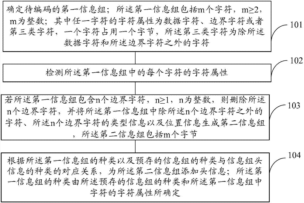
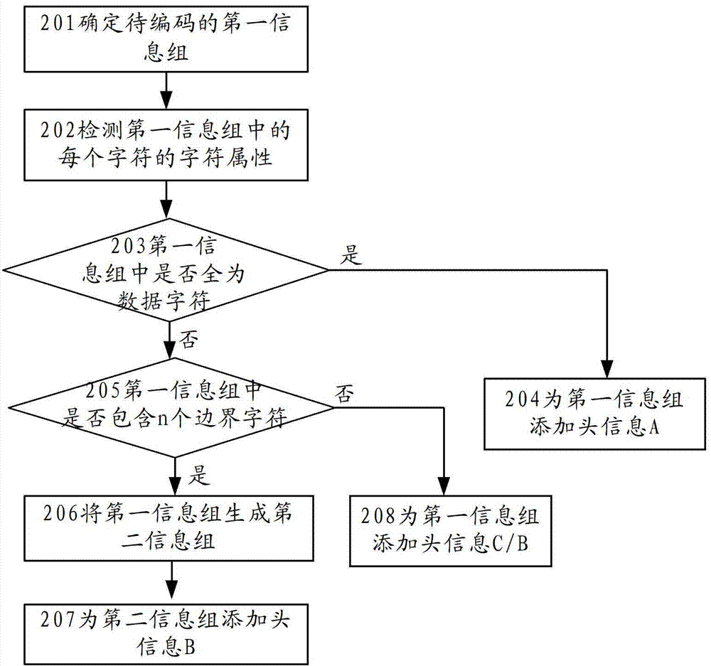
The invention discloses encoding and decoding method and device for an Ethernet physical layer, and relates to the technical field of communication. The method and device are used for improving the efficiency of encoding / deconding, and the flexibility in choosing the length of an information group which is to be encoded / decoded. The method provided by the invention comprises: determining a first to-be-encoded information group which comprises m characters, wherein m is an integer which is greater than or equal to two; setting any character as a data character, a boundry character or a third-type character, wherein one character occupies one byte; detecting the attribute of each character of the first information group; if the first information group comprises n boundry characters and n is an integer which is greater than or equal to one, deleting n boundry characters and generating a second information group by using the characters in the first information group except n boundry characters, the information of the types of the n boundry characters, and the position information of the n boundry characters, wherein the second information group comprises m bytes; and adding head information to the second information group.

Description

technical field [0001] The present invention relates to the technical field of communication, in particular to an encoding and decoding method and device for an Ethernet physical layer. Background technique [0002] Ethernet is a data link layer and physical layer technology for packet networking. The data link layer part of the Ethernet mainly includes the Media Access Control layer (Media Access Control, MAC for short) of the Ethernet. The physical layer of Ethernet mainly includes: Reconciliation Sub-layer (Reconciliation Sub-layer, referred to as RS), Media Independent Interface (Media Independent Interface, referred to as MII), Physical Coding Sublayer (Physical Coding Sublayer, referred to as PCS), physical media The connection sublayer (Physical Medium Attachment, referred to as PMA), the physical medium dependent sublayer (Physical Medium Dependent, referred to as PMD) and the interface between the physical media medium and each layer, etc., among which the RS is ad...

Claims


Application Information

Patent Timeline
IPC IPC(8): H04L1/00H04L45/74
CPCH04L1/004H04L1/0083H03M7/30H04L1/0079H04L45/74H04L69/323
Inventor 钟其文
Owner HUAWEI TECH CO LTD
Learn More