
Stamping device of corrugated foils and production device of corrugated foils

A stamping forming and foil technology, which is applied in the field of corrugated foil production equipment, can solve the problems of low automation of corrugated foil forming quality equipment and easy rebound in the forming process of corrugated foil, so as to ensure the quality of the formed surface and prevent rebound , Reduce the effect of work intensity

Active Publication Date: 2014-01-29
SHENZHEN INST OF ADVANCED TECH CHINESE ACAD OF SCI
View PDF7 Cites 12 Cited by
  • Summary
  • Abstract
  • Description
  • Claims
  • Application Information

AI Technical Summary

Problems solved by technology

[0004] The purpose of the present invention is to overcome the shortcomings of the above-mentioned prior art, and provide a corrugated foil stamping and forming device and corrugated foil manufacturing equipment with the stamping and forming device, which aims to solve the problems in the existing corrugated foil forming process. It is easy to rebound and cause technical problems that affect the forming quality of corrugated foil and the low degree of equipment automation

Method used


Image

  • Stamping device of corrugated foils and production device of corrugated foils
  • Stamping device of corrugated foils and production device of corrugated foils
  • Stamping device of corrugated foils and production device of corrugated foils

Examples


Embodiment Construction

[0025] In order to make the object, technical solution and advantages of the present invention clearer, the present invention will be further described in detail below in conjunction with the accompanying drawings and embodiments. It should be understood that the specific embodiments described here are only used to explain the present invention, not to limit the present invention.

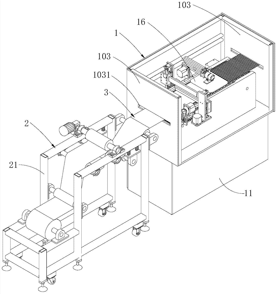
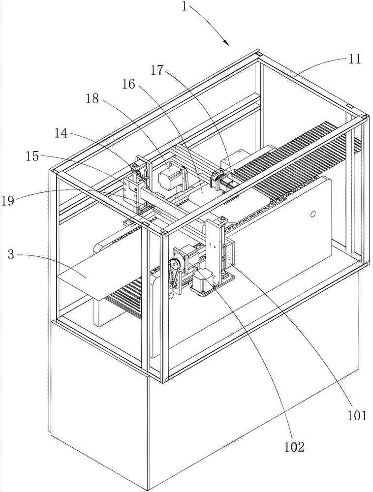
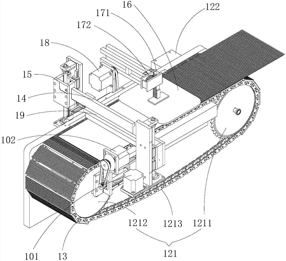
[0026] Such as Figure 1 ~ Figure 4As shown, the stamping and forming device 1 for corrugated foil 3 provided by the embodiment of the present invention includes a first frame 11, a conveying mechanism 12 installed on the first frame 11 and having a conveying member, and mounted on the conveying member The forming die 13 that is used to drive the foil 3 attached thereto to move and has a forming groove 131 is arranged above the forming die 13 for pressing the foil 3 into the forming groove 131 to make the foil 3 The formed forming stamping head 14, the first lifting assembly 15 installed on the fi...


PUM


Abstract

The invention is applied to the field of production equipment of corrugated foils and discloses a stamping device of corrugated foils. The stamping device comprises a first frame, a conveying mechanism, a forming die, a stamping head, a first lifting component, a pressure-holding shaping plate, and a second lifting component, wherein the conveying mechanism having a conveying component is mounted on the first frame, the forming die having a forming recess is mounted on the conveying component and capable of conveying and moving foils, the stamping head disposed above the forming die is used for pressing one foil into the forming recess to shape the foil, the first lifting component is used for driving the stamping head to ascend and descend, the pressure-holding shaping plate disposed above the forming die is used for pressure-held shaping of the shaped foil, and the second lifting component is used for driving the pressure-holding shaping plate to ascend and descend. A conveying direction of the pressure-holding shaping plate is behind the stamping head. The invention further discloses a production device of the corrugated foils. The production device comprises a shaping device of the corrugated foils and a conveying device used for conveying the foils to the stamping die. The stamping device and the production device have the advantages that production efficiency is high and shaping quality of the corrugated foils is good.

Description

technical field [0001] The invention belongs to the field of corrugated foil production equipment, in particular to a corrugated foil stamping device and corrugated foil manufacturing equipment with the stamping device. Background technique [0002] Honeycomb core material is a two-dimensional multicellular bionic material with honeycomb cell structure. It has the advantages of low density, low stiffness, strong impact resistance and controllable compression deformation. It is an ideal cushioning and energy-absorbing material. Due to its light weight and stable energy absorption characteristics, it is increasingly used in aerospace, national defense equipment, and rail transportation. However, the forming quality of the half-grid corrugated foil (such as semi-regular hexagonal corrugated foil) directly affects the bearing strength of the honeycomb core material and the ease of processing and manufacturing. If the forming quality of the half-grid corrugated foil is too poor, ...

Claims


Application Information

Patent Timeline
Patent Type & Authority Applications(China)
IPC IPC(8): B21D33/00B21D43/09B21D37/00B21D22/02
Inventor 罗昌杰于文泽岳伟玲王书付何凯杜如虚
Owner SHENZHEN INST OF ADVANCED TECH CHINESE ACAD OF SCI
Learn More