Light guide plate mould

A light guide plate and mold technology, which is applied in the field of light guide plate molds, can solve problems such as product quality degradation, mold surface damage, and broken molds, and achieve the effects of smooth flow, improved service life, and elimination of air bubbles

Inactive Publication Date: 2014-01-29
杨永明
View PDF0 Cites 15 Cited by
  • Summary
  • Abstract
  • Description
  • Claims
  • Application Information

AI Technical Summary

Problems solved by technology

[0003] 1. There is no sealing device in the mold cavity, and there is air, so that the plastic is affected by air resistance when flowing in the mold cavity, and the flow is difficult
[0004] 2. Due to the presence of air, the final product contains air bubbles and the

Method used


Image

  • Light guide plate mould

Examples


Embodiment Construction

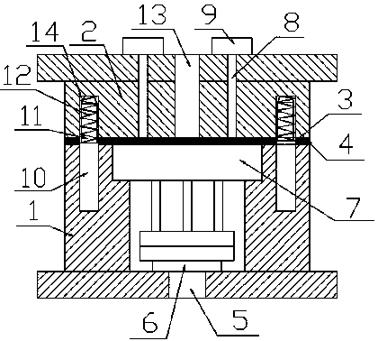
[0016] see figure 1 As shown, a light guide plate mold of the present invention includes a lower mold 1, an upper mold 2 arranged above the lower mold 1, a ejector pin hole 5 arranged at the bottom of the lower mold 1, and a sealing seal arranged at the position of the ejector pin hole 5. Bar 6, and the mold cavity 7 that is arranged in the lower mold 1, and the injection hole 13 that is arranged on the upper mold 2, and the exhaust hole 8 that is arranged in the upper mold 2 and communicates with the mold cavity 7, and is arranged in the row The vacuum exhauster 9 at the top of the air hole 8, the upper mold 2 and the lower mold 1 cooperate to form a parting surface 3, the parting surface 3 is provided with a sealing ring 4, and the upper mold 2 and the lower mold 1 A guide post is also arranged between, and a damping spring 12 is arranged on the guide post.

[0017] Wherein, the guide post is divided into a main body part 10 and a guide part 11, the damping spring 12 is arr...


PUM


Abstract

The invention discloses a light guide plate mould. The light guide plate mould comprises a lower mould, an upper mould arranged above the lower mould, an ejection rod hole formed in the bottom of the lower mould, a sealing strip arranged in the ejection rod hole, a mould cavity arranged in the lower mould, a material injection hole formed in the upper mould, an air exhausting hole which is formed in the upper mould and is communicated with the mould cavity, and a vacuum air pumping machine arranged at the top of the air exhausting hole, wherein the upper mould and the lower mould are matched to form a parting surface; the parting surface is provided with a sealing ring; a guide column is further arranged between the upper mould and the lower mould; the guide column is provided with a vibration absorption spring. With the adoption of the light guide plate mould, materials have no air resistance in the process of flowing in the mould cavity and the flowing is very smooth; no air exists in the mould cavity so that air bubbles in a product can be eliminated effectively; when the upper mould and the lower mould are closed, the vibration absorption spring can have a buffering effect and the mould is not damaged, so that the service life of the mould is prolonged.

Description

technical field [0001] The invention relates to a light guide plate mold. Background technique [0002] In the field of light guide plate molds, the structure of the existing light guide plate molds is relatively simple, only consisting of an upper mold and a lower mold. When working, after the upper mold and the lower mold are closed, the molten plastic is directly injected into the mold cavity by the injection molding machine to form the final product. There are following problems in this traditional way: [0003] 1. There is no sealing device in the mold cavity, and there is air, so that the plastic is affected by air resistance when flowing in the mold cavity, and the flow is difficult. [0004] 2. Due to the presence of air, the final product contains air bubbles and the quality of the product decreases. [0005] 3. When the upper mold and the lower mold are clamped, the clamping speed of the upper mold is fast, which may easily cause damage to the surface of the...

Claims


Application Information

Patent Timeline
IPC IPC(8): B29C45/34B29C45/84B29C33/30
CPCB29C45/34B29C45/2606B29C45/2608B29C45/844
Inventor 杨永明
Owner 杨永明
Why Eureka
Try Eureka