Wide-angle glaring lamp
A large-angle, light bulb technology, applied in the field of large-angle light-emitting light bulbs, can solve the problems of the light-emitting angle less than 180 degrees, and the LED light bulbs are not easy to dissipate heat, and achieve the effect of improving the light-emitting angle
- Summary
- Abstract
- Description
- Claims
- Application Information
AI Technical Summary
Problems solved by technology
Method used
Image

Examples
Embodiment 1
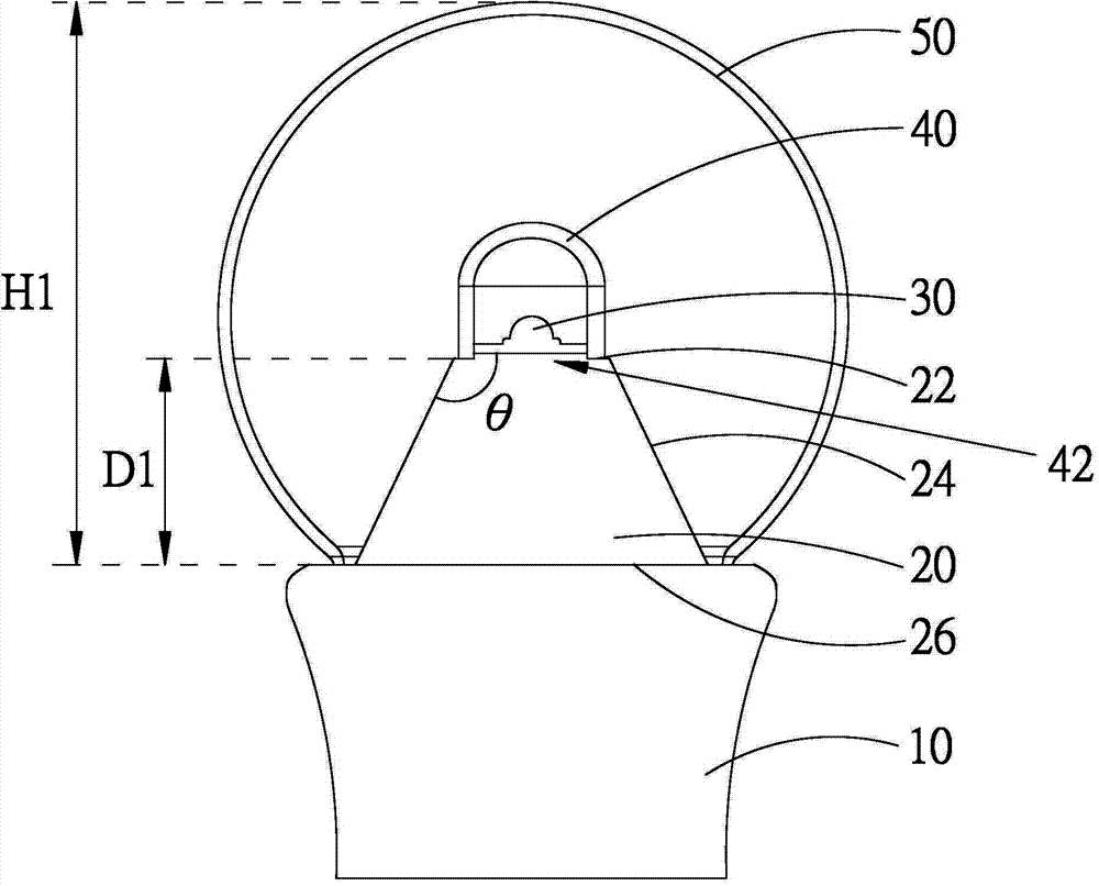
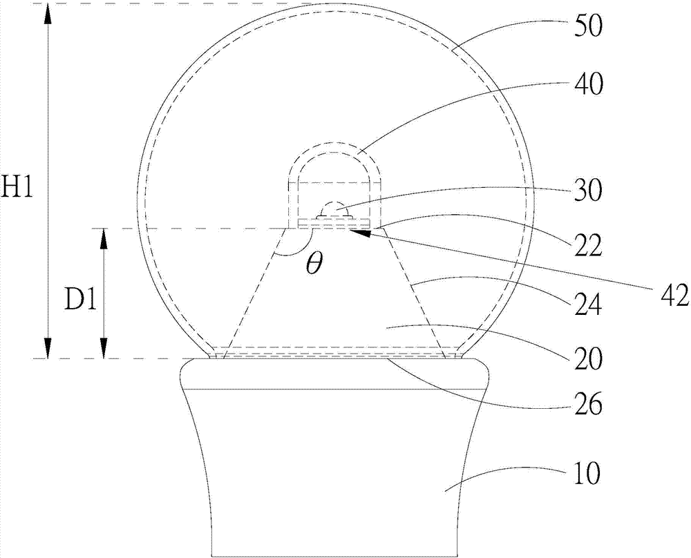
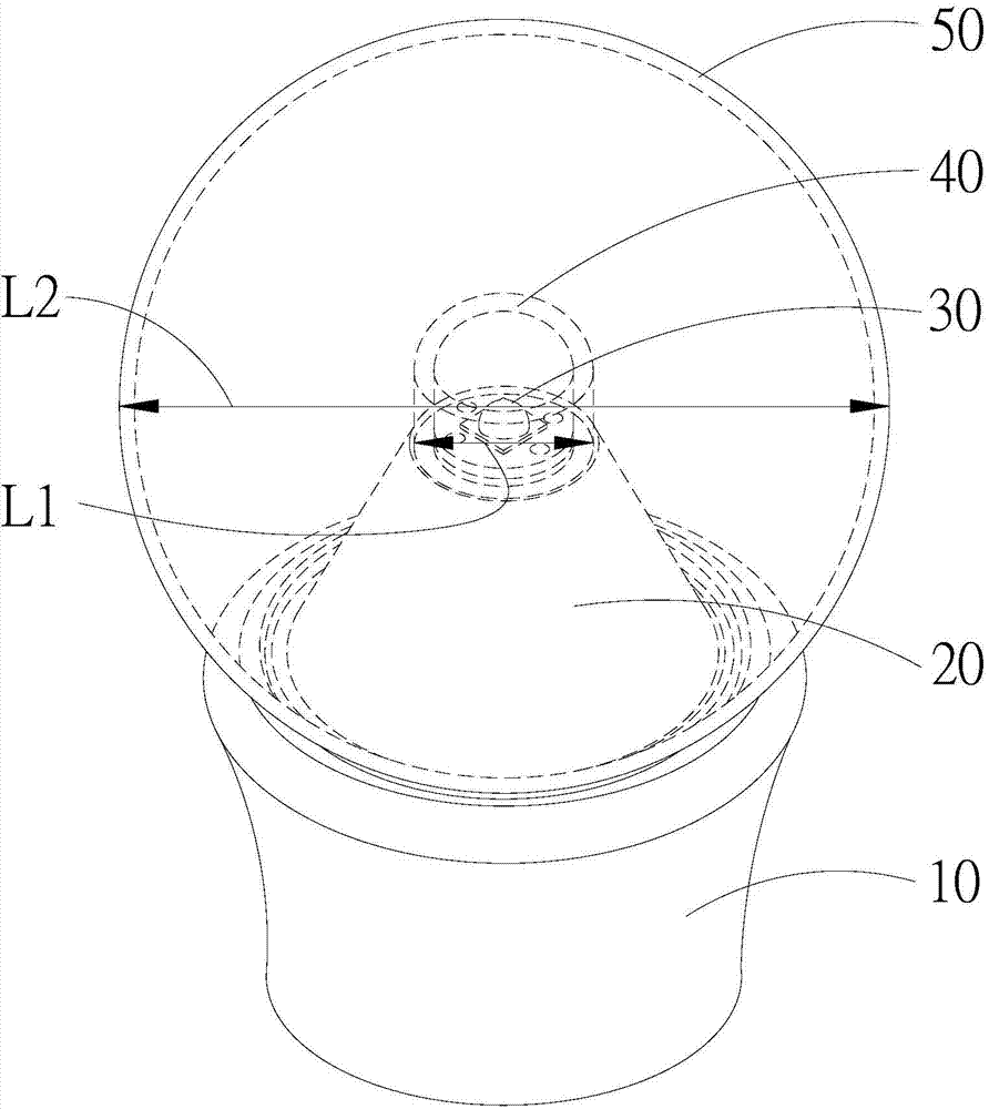
[0030] figure 1 and figure 2 , figure 1 It is a schematic cross-sectional view of Embodiment 1 of the large-angle light emitting bulb of the present invention, figure 2 It is a three-dimensional schematic diagram of Embodiment 1 of the large-angle light emitting bulb of the present invention. Such as figure 1 and figure 2 As shown, the large-angle light emitting bulb of the present invention includes a base 10, a mounting base 20 disposed on the base 10, at least one light-emitting unit 30, a fluorescent bulb 40, and a lampshade 50. The mounting base 20 has an upper surface 22, a side surface 24 and a lower surface 26, the side surface 24 is connected to the upper surface 22 and the lower surface 26, and the lower surface 26 of the mounting base 20 is connected to the base 10. The light-emitting unit 30 may be substantially a light-emitting diode chip, for example, and is disposed on the upper surface 22 of the mounting base 20. The fluorescent spherical shell 40 is disposed...
Embodiment 2
[0034] Compared with Embodiment 1, the difference of this embodiment is that the orthographic projection area of the lower surface 26 of the mounting base 20 on the base 10 can be greater than or equal to the orthographic projection of the upper surface 22 of the mounting base 20 on the base 10 Area, preferably, the orthographic area of the lower surface 26 of the mounting base 20 on the base 10 is greater than the orthographic area of the upper surface 22 of the mounting base 20 on the base 10, that is, the difference between the upper surface 22 and the side surface 24 The included angle θ is greater than 90 degrees. For example, such as figure 1 and figure 2 As shown, the angle θ between the upper surface 22 of the mounting base 20 and the side surface 24 may be 115 degrees, for example, and the orthographic projection area of the lower surface 26 of the mounting base 20 on the base 10 is larger than that of the mounting base The orthographic projection area of th...
Embodiment 3
[0036] Compared with Embodiment 1, the difference of this embodiment is that the vertical distance D1 from the upper surface 22 of the mounting base 20 to the base 10 is between 3 / 10 and 7 / 10 of the height H1 of the lampshade 50. Specifically, since the function of the mounting base 20 is to increase the height of the light-emitting unit 30 to increase the light-emitting angle of the bulb, the applicant of the present invention has found that when the distance D1 is between 3 / 10 of the height H1 of the lampshade 50 At 7 / 10, the light output angle of the bulb is the best. If the distance D1 is less than 3 / 10 of the height H1 of the lampshade 50, since the light is more likely to be blocked by the mounting base 20 and the base 10, in addition to the poor light angle of the bulb, the light-emitting unit 30 and the lampshade 50 are too far apart. It will cause a slight decline in luminous flux or change the light shape; and if the distance D1 is greater than 7 / 10 of the height H1 o...
PUM
 Abstract
Description
Claims
Application Information
 - Generate Ideas
- Intellectual Property
- Life Sciences
- Materials
- Tech Scout
- Unparalleled Data Quality
- Higher Quality Content
- 60% Fewer Hallucinations
Browse by: Latest US Patents, China's latest patents, Technical Efficacy Thesaurus, Application Domain, Technology Topic, Popular Technical Reports.
© 2025 PatSnap. All rights reserved.Legal|Privacy policy|Modern Slavery Act Transparency Statement|Sitemap|About US| Contact US: help@patsnap.com