Bidirectional throttling electronic expansion valve

An electronic expansion valve, two-way throttling technology, applied in the direction of high-efficiency regulation technology, fluid circulation arrangement, climate sustainability, etc., can solve the problems of increased cost of refrigeration system, inability to realize refrigerant circulation, etc., and achieve the effect of obvious cost advantage.

Active Publication Date: 2014-01-29
ZHEJIANG SANHUA INTELLIGENT CONTROLS CO LTD
View PDF4 Cites 8 Cited by
  • Summary
  • Abstract
  • Description
  • Claims
  • Application Information

AI Technical Summary

Problems solved by technology

[0006] The main disadvantage of the above-mentioned existing electronic expansion valve is: the electronic expansion valve can only realize the one-way flow of refrigerant, that is, flow out from the first connection pipe 11' to the second connection pipe 12' through the valve port 3', and cannot realize the flow of refrigerant. Flow from the second connection 12' to the first connection 11'
When used in a refrigeration system, a one-way valve needs to be connected, which increases the cost of the refrigeration system

Method used


Image

  • Bidirectional throttling electronic expansion valve
  • Bidirectional throttling electronic expansion valve
  • Bidirectional throttling electronic expansion valve

Examples


Embodiment Construction

[0024] The core of the present invention is to provide a two-way throttling electronic expansion valve. The structural design of the two-way throttling electronic expansion valve can adjust the refrigerant flow rate and realize the two-way circulation of the refrigerant.

[0025] In order to enable those skilled in the art to better understand the technical solutions of the present invention, the present invention will be further described in detail below in conjunction with the accompanying drawings and specific embodiments.

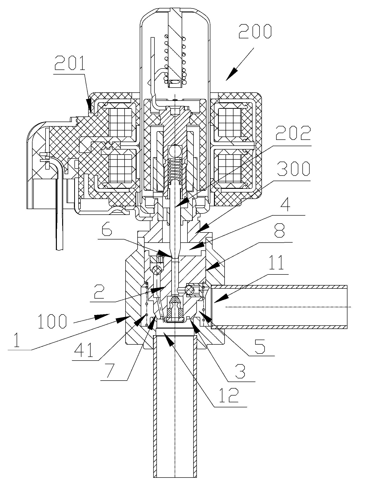
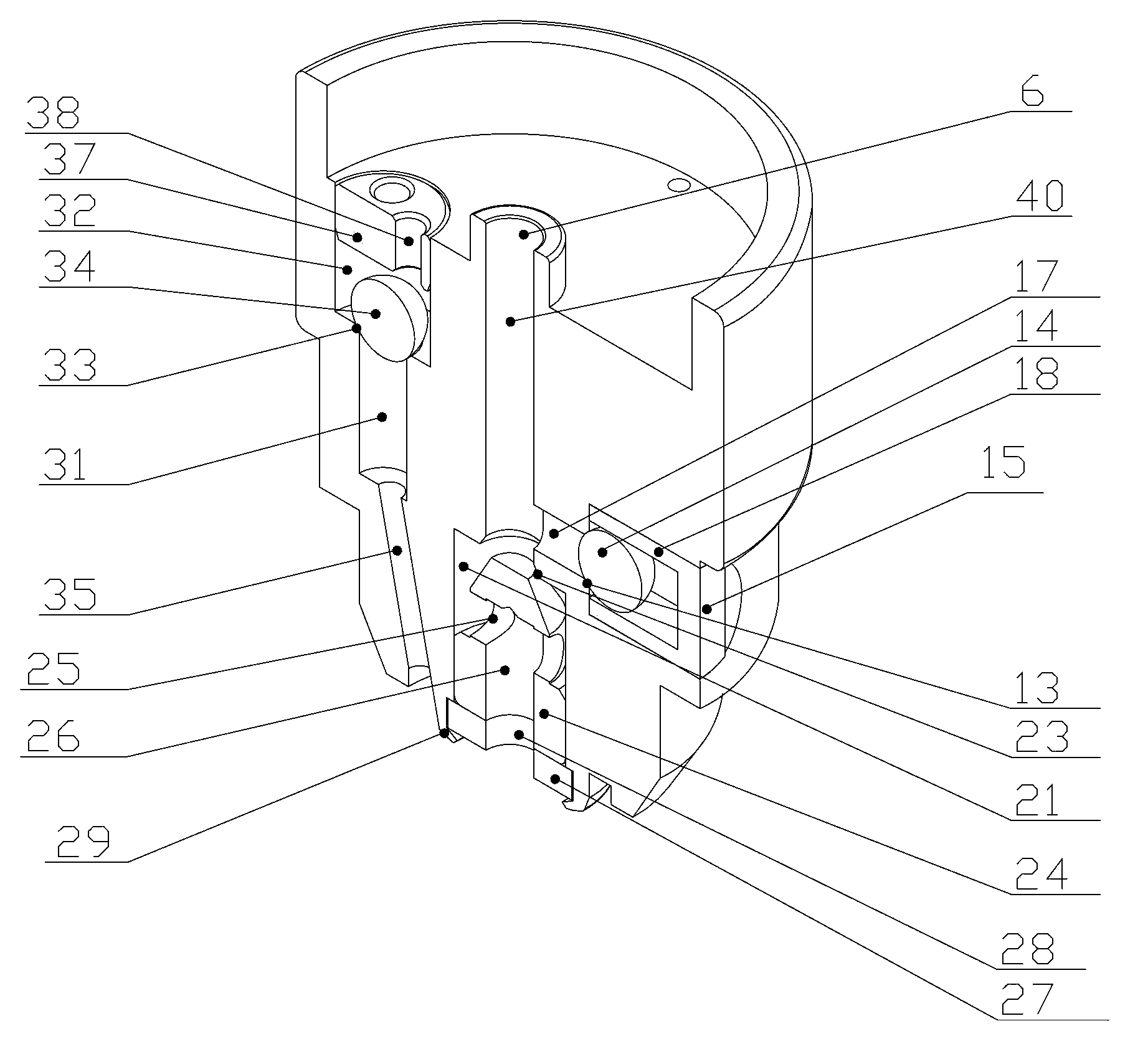
[0026] Please refer to figure 2 , image 3 , Figure 4 with Figure 5 , figure 2 A longitudinal sectional view of an embodiment of the two-way throttling electronic expansion valve of the present invention; image 3 for figure 2 Schematic diagram of the piston part of the middle two-way throttling electronic expansion valve; Figure 4 for image 3 The front plan view of the middle piston part; Figure 5 for image 3 Schematic diagram of the ...


PUM


Abstract

The invention discloses a bidirectional throttling electronic expansion valve. According to the bidirectional throttling electronic expansion valve, the flow of refrigerant can be adjusted, and the refrigerant can flow in a bidirectional mode. The bidirectional throttling electronic expansion valve comprises a main valve component and a pilot valve component. The main valve component comprises a main valve seat provided with a first connector and a second connector and a main valve opening formed in the main valve seat. The bidirectional throttling electronic expansion valve is characterized in that the main valve component further comprises a piston component, a valve cavity is divided by the piston component into an upper valve cavity and a lower valve cavity, an auxiliary valve opening part and a main valve element part are arranged on the piston component, the pilot valve component comprises a stepping motor and a valve shaft, a flow-in channel is formed between the upper valve cavity and the first connector, a first branch, a second branch and a third branch are formed in the piston component, the first branch enables the upper valve cavity to be communicated to the first connector in a unidirectional mode, the second branch enables the upper valve cavity to be communicated to the second connector in a unidirectional mode, and the third branch enables the second connector to be communicated to the upper valve cavity in a unidirectional mode.

Description

technical field [0001] The invention relates to the technical field of fluid control, in particular to a bidirectional throttling electronic expansion valve capable of arbitrarily and finely adjusting the refrigerant flow rate and allowing the refrigerant to flow in both directions. Background technique [0002] General electronic expansion valves can only flow and stop in one direction due to structural limitations. [0003] Such as figure 1 Shown is a longitudinal sectional view of an existing electronic expansion valve. The main structure of the electronic expansion valve is as follows: it includes a main valve 100' and a pilot valve 200'. The main valve 100' mainly includes a valve body 1' with a valve cavity connected with a first connecting pipe 11', a main valve core 2' with an inverted convex cross-section that can slide up and down in the valve body 1', and a welded seal. On the bottom of the valve body 1' there is a valve seat 4' with a valve port 3'. A second ...

Claims


Application Information

Patent Timeline
Patent Type & Authority Applications(China)
IPC IPC(8): F25B41/06F25B41/31
CPCY02B30/72Y02B30/70
Inventor 不公告发明人
Owner ZHEJIANG SANHUA INTELLIGENT CONTROLS CO LTD
Why Eureka
Try Eureka