Rotor structure of vehicular generator

A technology of rotor structure and generator, applied in the direction of magnetic circuit shape/style/structure, magnetic circuit rotating parts, etc.

Active Publication Date: 2014-01-29
JINZHOU HALLA ELECTRICAL EQUIP
View PDF6 Cites 4 Cited by
  • Summary
  • Abstract
  • Description
  • Claims
  • Application Information

AI Technical Summary

Problems solved by technology

[0003] It has the following problems: 1. During the assembly process of the rotor, the permanent magnet is directly inserted between the claw poles without any wrapping (or the wrapping scheme is not ideal), and the permanent magnet is easy to insert when inserted. Fracture or breakage will seriously affect the product yield and increase the production cost; 2. Even if the permanent magnet is not damaged during assembly, when the vehicle is working, due to the high temperature of the vehicle environment and the high rotor speed, etc., the front and rear claws are prone to damage. Deformation, the permanent magnet is easily crushed by the deformed claw pole, and the permanent magnet fragments enter the air gap, causing generator failure

Method used


Image

  • Rotor structure of vehicular generator
  • Rotor structure of vehicular generator
  • Rotor structure of vehicular generator

Examples


Embodiment 1

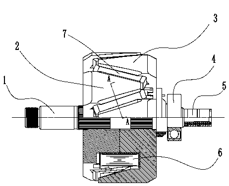
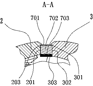
[0036] The front and rear ends and the bottom surface of the permanent magnet 702 are wrapped by the bottom shell 703, the top surface is wrapped by a metal support plate 701, and the front and rear ends of the bottom shell 703 are pasted by heat sealing (or glue coating) On the pole tip 204 of the front claw pole 2 and the pole tip 304 of the rear claw pole 3 . The left and right sides of the encapsulated permanent magnet 7 are respectively fixed by the side surface 201 of the front claw pole 2 and the lower surface 302 of the rear claw pole 3; the metal support plate 701 is positioned by the upper surface 203 of the front claw pole 2 and the side surface 301 of the rear claw pole 3; The bottom shell 703 is positioned by the lower surface 202 of the front claw pole 2 and the upper surface 303 of the rear claw pole 3 to achieve the purpose of fixing and encapsulating the permanent magnet 7 .

[0037] Example 2

Embodiment 2

[0039]The front and rear ends and bottom surface of the permanent magnet 702 are wrapped by the bottom shell 703, and the top surface is wrapped by a metal support plate 701. The front end of the bottom shell 703 is provided with a single hook 703a, and the rear end is provided with the single hook 703a. The hook 703a is a protrusion 703b with the hook mouth reversed, the single hook 703a is stuck at the pole tip 204 of the front claw pole 2, and the boss 703b is stuck at the pole tip 304 of the adjacent rear claw pole 3 or the single hook 703a is stuck on the pole tip 304 of the rear claw pole 3, and the boss 703b is stuck on the pole tip 204 of the adjacent front claw pole 2, so as to fix and package the permanent magnet 7 purposes.

[0040] Example 3

Embodiment 3

[0042] The front and rear ends and the bottom surface of the permanent magnet 702 are wrapped by the bottom shell 703, and the top surface is wrapped by a metal support plate 701. The front end of the bottom shell 703 is provided with double hooks 703c, and the rear end is provided with a boss 703b. One hook of the double hook 703c is stuck on the pole tip 204 of the front claw pole 2, the other hook is unfolded and stuck on the end of the side 301 of the rear claw pole 3, and the boss 703b is stuck on the On the pole tip 304 of the rear claw pole 3, or one hook of the double hook 703a is stuck on the pole tip 304 of the rear claw pole 3, and the other hook is unfolded and stuck on the side 201 end of the front claw pole 2 part, the boss 703b is clamped on the pole tip 204 of the front claw pole 2, so as to achieve the purpose of fixing and encapsulating the permanent magnet 7.


PUM


Abstract

A rotor structure of a vehicular generator comprises a rotating shaft, a front claw pole, a rear claw pole, a rear bearing, a collector ring, and an exciting coil assembly, wherein the front claw pole, the rear claw pole, the rear bearing, the collector ring and the exciting coil assembly are disposed on the rotating shaft. The front claw pole, the rear claw pole and the exciting coil assembly are press-fitted in a whole through the rotating shaft. The rotor structure is characterized in that a channel forms between each two adjacent claws of the front and rear claw poles, a packaged permanent magnet is fixed in each channel and made with a metal support plate, a permanent magnet member and a bottom shell by injection moulding, each permanent magnet member is disposed between the corresponding metal support plate and the corresponding bottom shell, and the bottom shells are made of plastic or nylon material. The rotor structure is simple to assemble, and damage of the permanent magnet member is prevented; compared to the existing rotor structure, the rotor structure has the advantages that yield of rotor production is increased and generator failure caused by the damage of the permanent magnet members occurs less likely.

Description

technical field [0001] The invention relates to a rotor structure in a vehicle generator. Background technique [0002] The rotor structure in the existing vehicle generator consists of a rotating shaft, a front claw pole, a rear claw pole, a rear bearing, a collector ring, and an excitation coil assembly, wherein the front and rear claw poles, the excitation coil assembly into one body by pressing the rotating shaft. In order to improve the power generation performance and power generation efficiency of the generator, permanent magnets are usually inserted between the front and rear claw poles of the rotor. [0003] It has the following problems: 1. During the assembly process of the rotor, the permanent magnet is directly inserted between the claw poles without any wrapping (or the wrapping scheme is not ideal), and the permanent magnet is easily broken or broken when inserted, which seriously affects the product yield and increases the production cost; 2. , Even if the ...

Claims


Application Information

Patent Timeline
Patent Type & Authority Applications(China)
IPC IPC(8): H02K1/27H02K1/28
Inventor 张志华孙玲鹿洪波陈静佟海川
Owner JINZHOU HALLA ELECTRICAL EQUIP
Why Eureka
Try Eureka