
Hydraulic soft start motor

A soft start and motor technology, applied in the field of electric motors, can solve the problems such as failure to implement energy saving and consumption reduction requirements, large selection of power, and failure to meet the original design requirements for debugging, so as to alleviate the impact of the starting current on the power grid, reduce the starting current, The effect of strong self-overload protection function

Active Publication Date: 2017-02-15
姚蓉 +1
View PDF7 Cites 0 Cited by
  • Summary
  • Abstract
  • Description
  • Claims
  • Application Information

AI Technical Summary

Problems solved by technology

In the past 20 years, products such as hydraulic transmission components and frequency conversion devices have developed rapidly in China, but the following situations exist in use: ① Load hydraulic components or frequency conversion devices between the motor and the working machine, which is difficult to install, troublesome to maintain, and relatively expensive High, especially after maintenance, debugging can not meet the original design requirements, customers feel inconvenience in use, and some even cancel hydraulic products and frequency conversion devices
② Many designers still use the principle of "big horse-drawn cart" to select motors when using motors for large inertia equipment; the selection of power is too large, resulting in reactive power loss and waste of energy
But the actual situation is that many designers or manufacturers still adopt the direct connection method between the power machine and the working machine in order to avoid trouble, so that the country's requirements for energy saving and consumption reduction cannot be implemented.

Method used


Image

  • Hydraulic soft start motor

Examples


Embodiment Construction

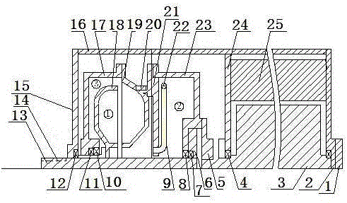
[0020] see figure 1 , the hydraulic soft start motor of the present invention is equipped with motor stator 25, motor rotor 3, front auxiliary chamber housing 23, pump wheel 19, worm wheel 18, rear auxiliary chamber housing 17 and output shaft in motor housing 16 13. The motor rotor 3 is connected and fixed to the front auxiliary chamber casing 23 through the connecting plate 5, the front auxiliary chamber casing 23 is connected and fixed to the pump wheel 19 through the connecting plate 5, and the pump wheel 19 is connected and fixed to the rear auxiliary chamber casing 17. The worm wheel 18 is connected and fixed with the output shaft 13; the pump wheel 19 and the worm wheel 18 constitute the soft start working chamber, the worm wheel 18 and the rear auxiliary chamber housing 17 form the rear auxiliary chamber, and the front auxiliary chamber housing 23 and the pump wheel 19 form the front auxiliary chamber. The front auxiliary chamber communicates with the soft start workin...


PUM


Abstract

The invention discloses a hydraulic soft starting motor. A motor stator, a motor rotor, a front auxiliary chamber shell, a pump wheel, a worm gear, a rear auxiliary chamber shell and an output shaft are arranged in the motor shell. The motor rotor, a connection plate, the front auxiliary chamber shell, a connection board and the pump wheel are sequentially connected for transmission. The pump wheel is further connected and fixed with the rear auxiliary chamber shell, and the worm gear is connected and fixed with the output shaft. A soft starting working cavity is composed of the pump wheel and the worm gear, a rear auxiliary chamber is composed of the worm gear and the rear auxiliary chamber shell, and a front auxiliary chamber is composed of the front auxiliary chamber shell and the pump wheel. The front auxiliary chamber is communicated with the working cavity through a guiding pipe, and a throttling valve is installed at the upper end of the guiding pipe. The rear auxiliary chamber is communicated with the working cavity, and the working cavity, the front auxiliary chamber and the rear auxiliary chamber are filled with working liquid. The hydraulic soft starting motor is stable and light in starting, short in starting time, low in current and capable of saving energy and reducing consumption, and impact on an electric grid is small. In addition, the hydraulic soft starting motor has the functions of load balance and overload protection.

Description

technical field [0001] The invention relates to the technical field of electric motors, in particular to a new electric motor with hydraulic transmission function—a hydraulic soft-start motor, which has the advantages of smooth and brisk start, short start-up time, low start-up current, small impact on power grid, overload protection and balanced load advantage. Background technique [0002] 1) Asynchronous motors, especially squirrel-cage motors, although simple in structure, durable, cheap and good in characteristics, have poor starting performance, which is mainly manifested in two aspects: ①The starting torque is low, and the general standard squirrel-cage The starting torque of the motor (ordinary Y series motor) is about 1.3∽1.8 times the rated torque; Premature failure of the insulation causes the grid voltage to drop; especially in the use of large inertia equipment, a larger power motor has to be selected, resulting in a loss of reactive power. [0003] 2) With th...

Claims


Application Information

Patent Timeline
Patent Type & Authority Patents(China)
IPC IPC(8): H02K7/118F16H41/24
Inventor 潘志勇
Owner 姚蓉
Learn More