
Linear drive

A technology of linear drive and moving direction, which is applied in the direction of firework actuation device, transportation and packaging, seat belts in the car, etc., can solve the problems of expensive linear drive device, prolonged manufacturing time, and radial holes 26 costing work steps, etc.

Active Publication Date: 2014-01-29
TRW AUTOMOTIVE GMBH
View PDF6 Cites 0 Cited by
  • Summary
  • Abstract
  • Description
  • Claims
  • Application Information

AI Technical Summary

Problems solved by technology

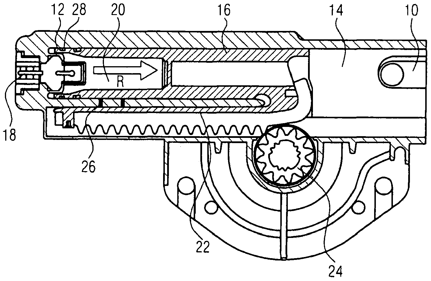
[0009] The production of the radial bore 26 requires relatively complex work steps, which prolongs the production time and thus makes the linear drive expensive

Method used


Image

  • Linear drive
  • Linear drive

Examples


Embodiment Construction

[0026] FIG. 1 , which has already been described in detail in the introduction, shows a known linear drive.

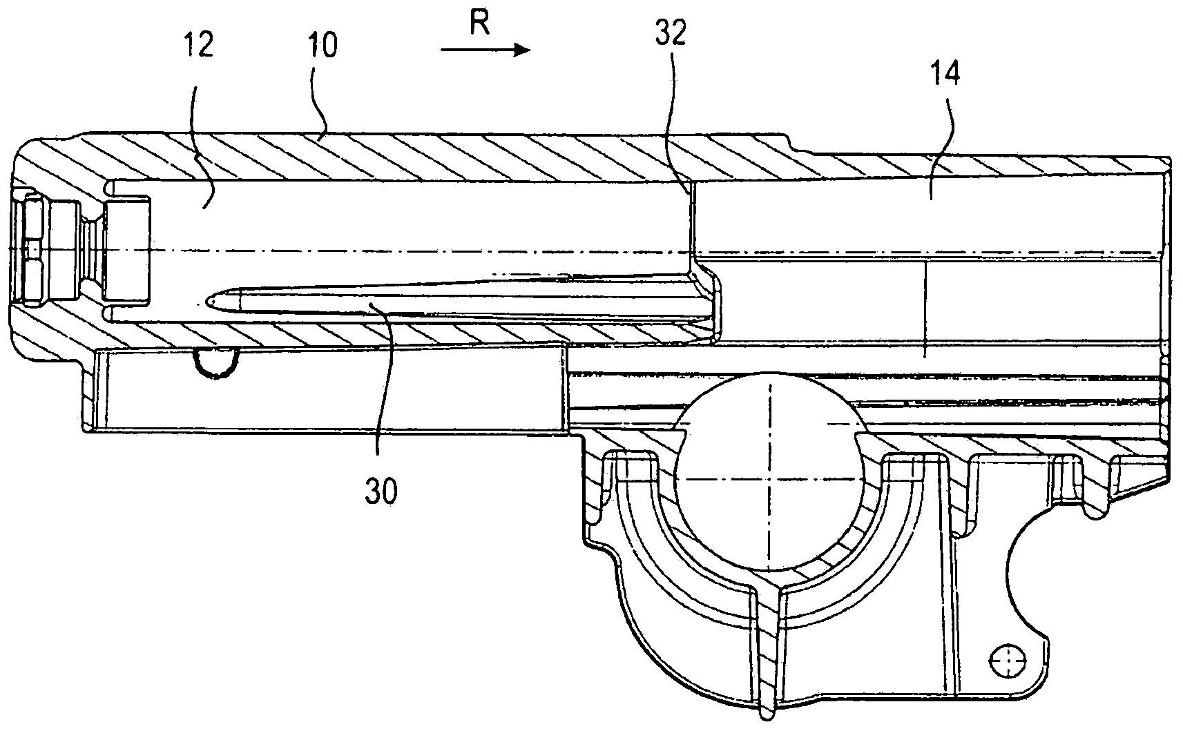
[0027] exist figure 2 The linear drive according to the invention shown in FIG. 1 differs from the linear drive shown in FIG. 1 essentially in how the gas escapes from the piston receptacle. exist figure 2 Components not shown in can be designed as shown in known linear drives. For this reason, the previously introduced reference numerals also continue to be used in figure 2 Components of the linear drive device according to the invention.

[0028] The housing 10 of the linear drive has a piston receptacle 12 and a cavity 14 adjoining directly thereto in the axial direction, into which cavity a piston element 16 , not shown here, moves as it moves in the direction of movement R . The cavity 14 is fluidically connected to the surroundings of the linear drive.

[0029] A rack 22 , likewise not shown, drives a pinion 24 , likewise not shown, which is connected to a ...


PUM


Abstract

A linear drive, in particular for a seatbelt pretensioner, has a housing (10) with a piston receptacle (12), a piston element (16) which is accommodated in the piston receptacle (12) in a displaceable fashion, and a pyrotechnic drive element which can supply gas for displacing the piston element (16). The inner wall of the piston receptacle (12) has a groove (30) which extends in the direction (R) of displacement of the piston element (16) and through which gas can flow out of the piston receptacle (12).

Description

technical field [0001] The invention relates to a linear drive device, in particular to a linear drive device for a seat belt tensioner. Background technique [0002] In linear drives, which are used as mechanical drive elements, the driven piston traverses a predetermined travel path. The linear movement can be used directly in a push or pull movement, for example to retract a seat belt lock. However, the linear movement can also be converted into a rotational movement, for example by means of a toothed rack, in order to turn, for example, a belt reel of a belt retractor. [0003] The energy of motion is here generated by the combustion of a pyrotechnic propellant and the expansion of the hot gas formed here. The release of the gas must be adapted to the parameters that determine the movement of the moving piston, such as housing dimensions and mass, in order to achieve an optimized acceleration and an optimized force transmission of the piston. It has proven to be advan...

Claims


Application Information

Patent Timeline
Patent Type & Authority Applications(China)
IPC IPC(8): B60R22/195B60R22/46
CPCB60R2022/4661B60R22/4633F15B15/19
Inventor S·施赖伯H·格劳K·克鲁科夫斯基
Owner TRW AUTOMOTIVE GMBH
Learn More