Thermal Transistor

A heat pipe and volume technology, used in heat transfer modification, heat exchange equipment, indirect heat exchangers, etc., can solve the problem of difficult connection of heat pipes with multiple heat sources, and achieve the effect of simple structure, simplified manufacturing process and low manufacturing cost.

Inactive Publication Date: 2015-08-26
克莱米特威尔上市有限公司
View PDF5 Cites 3 Cited by
  • Summary
  • Abstract
  • Description
  • Claims
  • Application Information

AI Technical Summary

Problems solved by technology

[0008] A further problem with the prior art is that the construction of heat pipes is not easily manufactured in different sizes on an industrial scale
[0009] Another problem with the prior art is that multiple heat sources with different or slightly different temperatures are difficult to connect to the same heat pipe

Method used


Image

  • Thermal Transistor
  • Thermal Transistor
  • Thermal Transistor

Examples


Embodiment 1

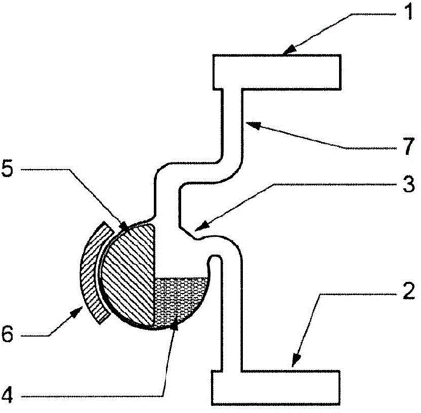
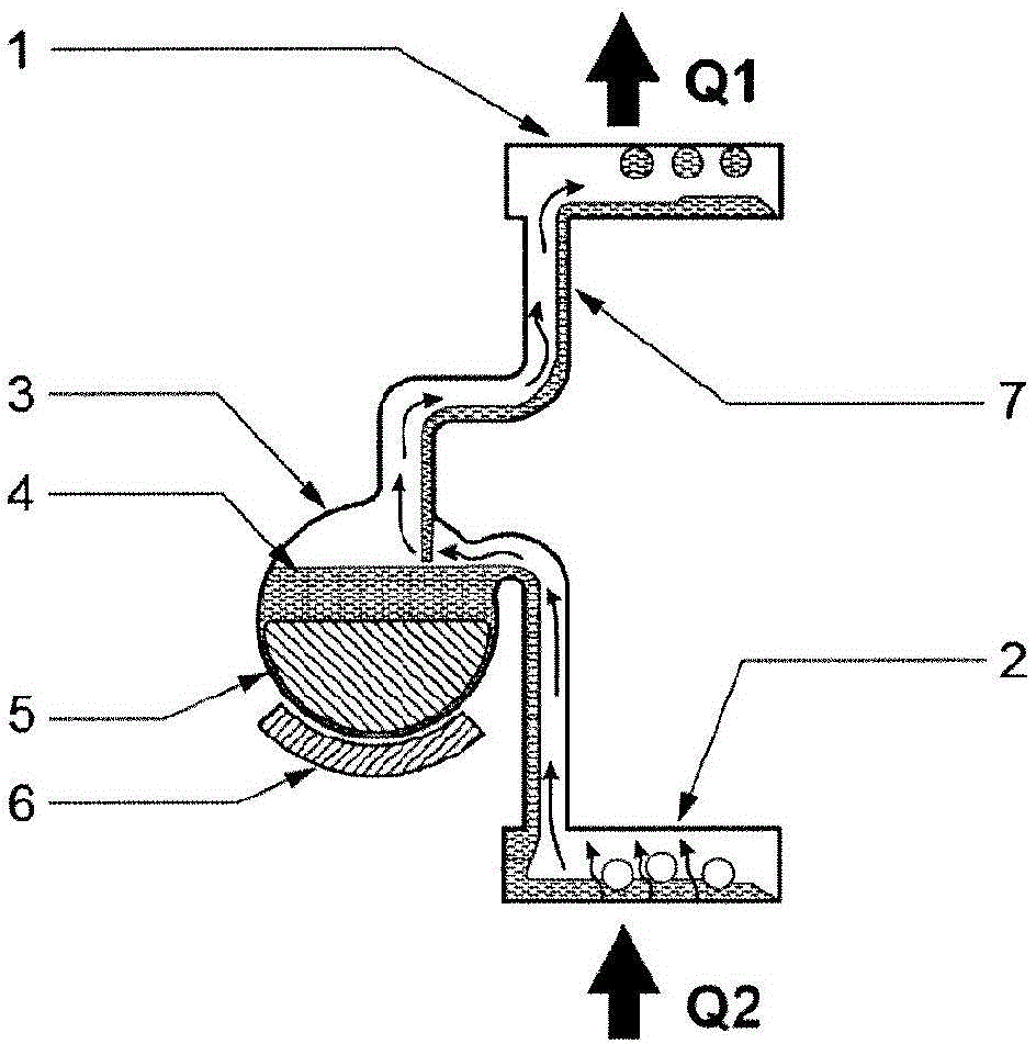
[0082] The heat pipe will now be described in more detail by giving a non-limiting example, with reference to Figure 1a , 1b , where 1 denotes a condenser, 2 denotes an evaporator, 3 denotes a replacement container, 4 denotes a working fluid, 5 denotes a floating body with a magnet, 6 denotes a magnet, and 7 denotes a tube for transporting a gas-phase working fluid and a liquid-phase working fluid. Q1 and Q2 represent the energy transferred from the condenser and the energy transferred to the evaporator, respectively. The condenser 1 is located in the upper part and is represented as a vessel in which the steam is condensed. The evaporator 2 is located in the lower part where heat is applied to the surface area causing evaporation of the working fluid. The third part is the displacement container 3, in which the working fluid 4 is stored when the heat pipe is in the off mode. In more detail, the working fluid 4 is stored in the lower part of the displacement container, indi...

Embodiment 2

[0085] The heat pipe will now be described in more detail by giving a non-limiting example, with reference to Figure 5 . External heat pipes are thermally connected to the heat pipes, in particular to the evaporation regions e1-e6 of the heat pipes. The condenser sections of the external heat pipes h1-h6 are in thermal contact with the evaporation zones e1-e6, respectively. The external heat pipes are in thermal contact with different chemical heat pumps that work in a two-step process, including heat storage and heat release. Chemical heat pumps are set up to store heat from any heat source. Examples of heat sources include, but are not limited to, the sun, gas heaters, oil burners, electric heaters, coal fired stoves, and wood stoves. During the exothermic process, heat can be transferred to the heat pipe via the external heat pipe and further to the desired destination. When the chemical heat pump stores energy through the heat source, the heat transfer is switched off...

Embodiment 3

[0087] The heat pipe will now be described in more detail by giving a non-limiting example, with reference to Figure 6 . Each of the two chemical heat pumps works in a two-step process and each includes a reactor section, and two heat pipes are arranged to transfer heat from the two chemical heat pumps to the water heater. A heat pipe is according to the invention and can be adjusted and switched on and off. Heat can also be transferred to one of the reactors from an external heat source, see Figure 6 .


PUM


Abstract

A heat pipe comprises a condenser, an evaporator, a working fluid, a displacement vessel and at least one connecting pipe. The volume available for the working fluid inside the displacement vessel is adjustable, said volume being adapted to change by a rotating movement of a body.In one embodiment external heat pipes allow several different heat sources to be connected. Advantages include that the capability of transferring heat can be adjusted and fine tuned to the desired value. Less force is required to rotate the body inside the displacement vessel. No energy input is required to hold the body in a desired position. The construction is simple and inexpensive to manufacture. In particular the construction is easy to manufacture in different volumes, since the diameter of the displacement vessel and rotating body can be the same but with a longer displacement vessel.

Description

technical field [0001] The present invention generally relates to an improved heat pipe that can be tuned and has expanded energy intake capabilities. Background technique [0002] Generally, adsorption machines (including adsorbers and absorbers) operating intermittently use a two-step process. In the first step, the reactor of the adsorption machine is heated, which is called the heat storage step. In the second step, the reactor of the adsorption machine is cooled, which is called the exothermic step. If the adsorption machine consists of several units, there must be a good thermal connection between them, taking into account possible temperature differences between the different heat sources. Adsorption machines (ie chemical heat pumps) typically include a reactor. In order to achieve good performance of the adsorption machine, the energy transfer to and from the adsorption machine reactor must be unimpeded. For this reason, it is important to have good thermal conta...

Claims


Application Information

Patent Timeline
IPC IPC(8): F28D15/02F28D15/06
CPCF28D15/06F28D15/0266F28F2013/008F28D15/02
Inventor 格兰·博林
Owner 克莱米特威尔上市有限公司
Why Eureka
Try Eureka