Hydraulic test sealing structure of pressure container and mounting and use method of hydraulic test sealing structure

A hydrostatic test and pressure vessel technology, applied to pressure vessels, using stable tension/pressure to test material strength, fixed-capacity gas storage tanks, etc., can solve the problems of no pressure test channel structure design cases, etc.

Active Publication Date: 2014-02-05
DONGFANG (GUANGZHOU) HEAVY MASCH CO LTD
View PDF5 Cites 5 Cited by
  • Summary
  • Abstract
  • Description
  • Claims
  • Application Information

AI Technical Summary

Problems solved by technology

[0009] At present, there is no corresponding or similar pressure

Method used


Image

  • Hydraulic test sealing structure of pressure container and mounting and use method of hydraulic test sealing structure
  • Hydraulic test sealing structure of pressure container and mounting and use method of hydraulic test sealing structure

Examples


Embodiment Construction

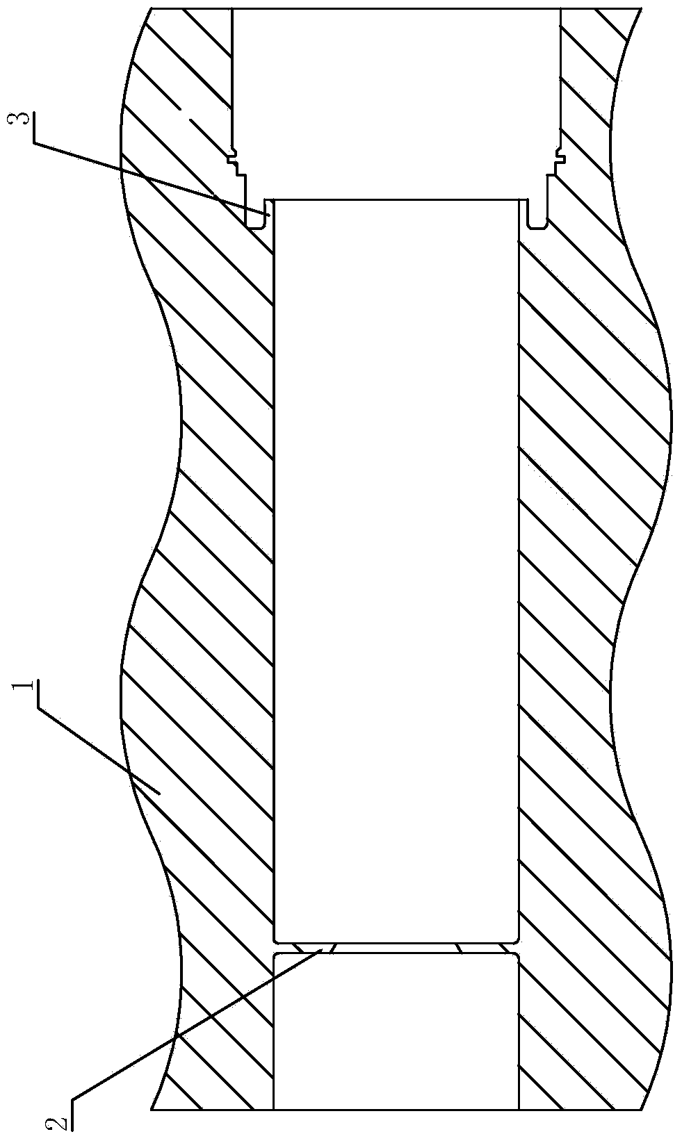
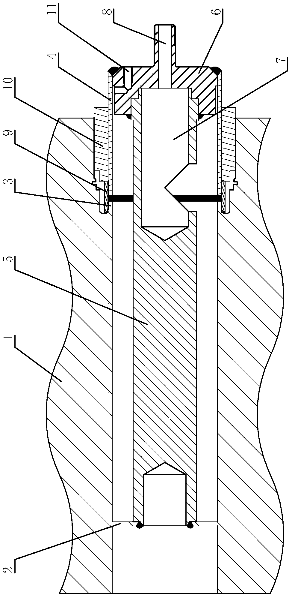
[0030] like figure 2 The hydraulic test sealing structure of the pressure vessel includes a vessel body 1 with a cylindrical inner cavity. A 3.75 mm thick annular groove thin wall 3 is provided on the rear side of the cylindrical inner chamber, and a hydraulic connection pipe 4 is sealed and welded at the rear end of the thin wall 3 . The welding seal between the hydraulic joint 4 and the thin wall 3 is because the hydraulic test seal at the thin wall 3 cannot be realized by mechanical sealing; and the original design function of the thin wall 3 is to connect and weld Water pipes are used. The thin wall 3 has reserved a certain length margin in the previous processing, which is used for the welding water crimping pipe 4 in the hydraulic test. The welding of the hydraulic connection pipe 4 and the thin wall 3 is realized by using an automatic TIG welding machine that can rotate around the axis.

[0031] The front side of the cylindrical inner cavity is provided with a 4mm t...


PUM


Abstract

The invention relates to a hydraulic test sealing structure of a pressure container. The hydraulic test sealing structure comprises a container body with a cylindrical cavity, wherein an annular fin is arranged in front of the cylindrical cavity; an annular groove type thin wall is arranged behind the cylindrical cavity; the rear end of the thin wall is hermetically welded with a hydraulic pressure connecting pipe; a sealing core rod penetrates into the cylindrical cavity from back to front and then is hermetically welded with the annular fin; the rear end of the sealing core rod is fixedly connected with a plug; the plug is positioned in the hydraulic pressure connecting pipe and is fixedly connected with the hydraulic pressure sealing pipe; the rear part of the sealing core rod is provided with a drainage cavity which is communicated with the cylindrical cavity; the plug is provided with a water injection hole for communicating the drainage cavity with the exterior. The invention also relates to a mounting and use method of the sealing structure. The invention provides the hydraulic test sealing structure and the mounting and use method aiming at an unconventional pressure container, so that effective sealing of a water outlet of the pressure container is realized, smooth pressure test of the pressure container is guaranteed, and the dimensional accuracy meets the requirements after hydraulic test. The hydraulic test sealing structure can be applied to hydraulic test sealing.

Description

technical field [0001] The invention relates to the field of hydraulic test sealing, in particular to a hydraulic test sealing structure of a pressure vessel and an installation and use method thereof. Background technique [0002] On a certain unconventional pressure vessel, there is a special water outlet structure as follows, such as figure 1 shown; [0003] Its characteristics can be summarized as the following points: [0004] (1) The water outlet structure has two openings, which are respectively located on the front side and the rear side of the container body 1. When the container is subjected to a hydraulic test, the front and rear side openings must be sealed; [0005] (2) The feature of the front side opening is that a ring fin 2 with a thickness of less than 5mm is provided in the deep cylindrical cavity. quantity. [0006] (3) The rear opening is characterized by a ring-shaped thin wall 3 with a thickness of less than 5mm. The length of the thin wall is much...

Claims


Application Information

Patent Timeline
IPC IPC(8): F16J13/00G01N3/12
Inventor 唐伟陈耀茂邓智勇孙勇马文超
Owner DONGFANG (GUANGZHOU) HEAVY MASCH CO LTD
Why Eureka
Try Eureka