
A heat distribution method and system for a central heating system in an on-off regulation mode

A centralized heating and heating technology, applied in heating systems, household heating, space heating and ventilation, etc., can solve the problems of limited popularization and application, less heat shared by radiators, unreasonable heat sharing, etc. Apportionment of reasonable and acceptable effects

Active Publication Date: 2015-10-07
北京暖流科技有限公司
View PDF2 Cites 0 Cited by
  • Summary
  • Abstract
  • Description
  • Claims
  • Application Information

AI Technical Summary

Problems solved by technology

[0003] (1) The user's private modification of the radiator or insufficient design precision of the radiator will cause unreasonable heat distribution
The reasonable premise of "on-off time area method" is that the actual area of ​​the radiator completely matches the required area, but the actual situation is that on the one hand, there is inevitably a certain degree of error in the design itself, and on the other hand, users modify and increase without permission. The phenomenon of radiators is common. As a result, users with large radiators share less heat and pay less heat bills; on the contrary, users with smaller radiators share more heat and pay more heat bills. Objectively existing unreasonable phenomena lead to the "on-off time area method" that apportions heat according to the cumulative opening time of the valve and the heating area cannot be fully accepted by users, and its promotion and application are limited
[0004] (2) The difference between the user's actual flow and the design flow will cause unreasonable heat distribution
Another prerequisite for the reasonable heat allocation of the "on-off time area method" is that the actual flow of the user needs to fully match the demand flow, but the actual situation is that there is inevitably a certain degree of error in the design itself, and it is difficult to achieve the design flow. On the other hand, due to the congenital imbalance of the heat user itself, it is necessary to install an artificial adjustment system and carry out fine manual adjustments to make the "on-off time method" meet better accuracy requirements, and this is true in actual engineering. It is also difficult to achieve in the same way. Often some users have more traffic than demand, and some users have less traffic than demand, which will cause users with more traffic to share less calories, and users with less traffic to share more calories. The "on-off time area method" of accumulative opening time of the valve and apportionment of heat by the heating area cannot be accepted by users, and its promotion and application are limited
[0005] (3) In the actual operation process, users with higher room temperature will transfer heat to adjacent rooms with lower room temperature, which will cause the valve opening time of users with high room temperature to increase compared with the normal heating of neighbors, and more heat will be shared. This unreasonable situation If the difference is large, the "on-off time area method" that apportions heat according to the cumulative opening time of the valve and the heating area cannot be accepted by users, and its promotion and application will be limited.
[0010] To sum up, there are still many problems that have not been solved or overcome at present, according to the "on-off time area method" of apportioning heat according to the cumulative opening time of the valve and the heating area.

Method used


Image

  • A heat distribution method and system for a central heating system in an on-off regulation mode
  • A heat distribution method and system for a central heating system in an on-off regulation mode
  • A heat distribution method and system for a central heating system in an on-off regulation mode

Examples


Embodiment Construction

[0084] The technical scheme of the present invention will be further described in conjunction with drawings and examples below, but it does not constitute a restriction to the claims of the present invention:

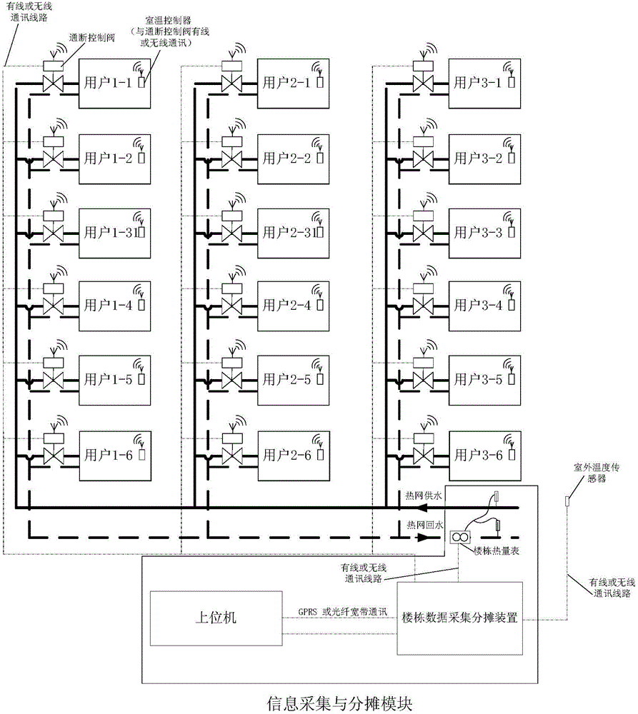
[0085] Such as figure 2As shown, the heat meter at the thermal entrance of the building measures the total heat of the building, and uses this as the basis for the heating charge of the building. Install a room temperature on-off control valve on each user branch pipeline, and set a room temperature controller in the room. The room temperature controller measures the room temperature and at the same time transmits the measured room temperature signal and the room temperature signal set by the user to the room temperature on-off control valve through wireless or wired means, and the room temperature on-off control valve controls the on-off of the valve through its built-in room temperature control strategy , so as to control the user's room temperature, and calculate t...


PUM


Abstract

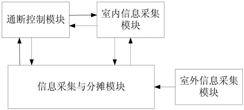
The invention relates to a heat apportionment method and system of a central heating system under an on-off regulation mode. The heat apportionment method comprises the following steps of carrying out the computation of the heating heat consumption according to an on-off time area method, and modifying each household valve opening duty ratio according to an embedded special computation method by utilizing real-time measured user indoor temperature and outdoor temperature, so as to compute each household apportioned heat by utilizing each modified household valve opening duty ratio. The heat apportionment system comprises an indoor information collection module, an on-off control module, an information collection and apportionment module and an outdoor information collection module, wherein the indoor information collection module is used for measuring the indoor temperature, the outdoor information collection module is used for measuring the outdoor temperature, the on-off control module is used for carrying out on-off control on a valve according to the indoor temperature fed back by the indoor information collection module, the outdoor information collection module is used for sending the collected outdoor temperature to the information collection and apportionment module, and the information collection and apportionment module is used for carrying out the heat apportionment according to the heat apportionment method disclosed by the invention.

Description

technical field [0001] The invention relates to a method for apportioning heat in a central heating system based on an on-off adjustment mode, and belongs to the field of heating, ventilation and air conditioning. Background technique [0002] The "heat supply reform" centered on "household adjustment" and "metering and charging" is an important part of my country's building energy conservation work. JCJ173-2009" and Chinese patent "A Method and System for Simultaneously Realizing Heat Regulation and Heat Metering" (Application No. 200610114686.2 Application Date 2006.11.21), provide a user heat allocation of "on-off time area method" measurement method. This method achieves the purpose of controlling the room temperature by on-off control of the user's heating circulating water. At the same time, based on the accumulated valve opening time and heating area of ​​each heating user, the heating heat consumption of the entire building is allocated and charged according to the he...

Claims


Application Information

Patent Timeline
Patent Type & Authority Patents(China)
IPC IPC(8): F24D19/10
Inventor 不公告发明人
Owner 北京暖流科技有限公司
Learn More