Negative ion emission device and air purifying equipment of negative iron emission device

A negative ion emission and air technology, which is applied in the direction of electrical components, deodorization, disinfection, etc., can solve the problems that the content of negative ions cannot meet the requirements, the intensity of negative ion emission is not concentrated enough, and the emission of negative ions is unstable, so as to improve the effect of purifying air and improve production Hygienic requirements, low cost effect

Active Publication Date: 2014-02-05
浙江纳尔瓦智能科技有限公司
View PDF7 Cites 9 Cited by
  • Summary
  • Abstract
  • Description
  • Claims
  • Application Information

AI Technical Summary

Problems solved by technology

However, because the nano-carbon fiber bundles are composed of nano-carbon fibers and are directly fixed in the electrode holes, once the fiber bundles loosen or fall off, the negative ion emission will be unstable and the process is not mature enough; and it is not easy to place new nano-carbon fiber bundles on the electrode again. In the hole, it is not easy to maintain, and the service life of the equipment is short; in addition, the nano-carbon fiber bundles are not concentrated enough to emit negative ions
[0004] The air purification equipment using the above negative ion emission device emits unstable negative ions, is not easy to maintain, has a short service life, the negative ion emission distance and the content of negative ions in the air cannot meet the requirements, and the structure is not simplified enough.

Method used


Image

  • Negative ion emission device and air purifying equipment of negative iron emission device
  • Negative ion emission device and air purifying equipment of negative iron emission device
  • Negative ion emission device and air purifying equipment of negative iron emission device

Examples


Embodiment Construction

[0028] The present invention will be further described below in conjunction with accompanying drawing.

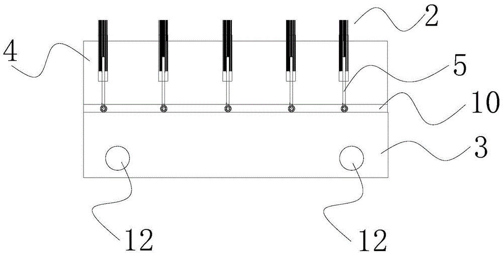
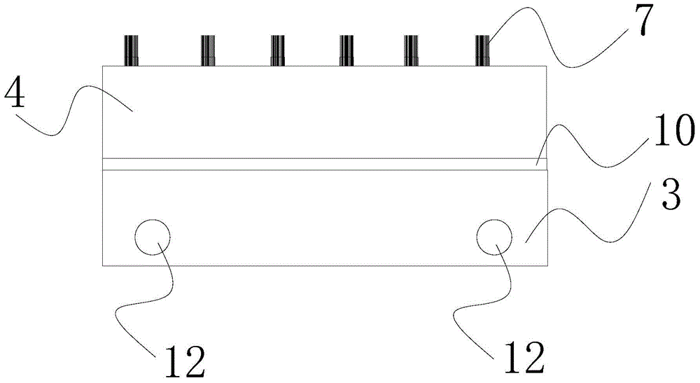
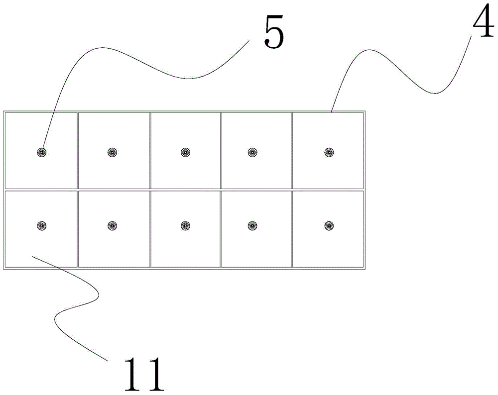
[0029] see figure 1 , figure 2 , image 3 , Figure 4 and Figure 5 , the present invention is a negative ion emitting device 19, the negative ion emitting device 19 includes a conductive structure 1 and a plurality of emitting heads 2, the conductive structure 1 includes a conductive copper plate 3, an insulating socket slot 4 and a conductive pin 5, and the emitting head 2 includes an insulating package Tight layer 6, nano carbon fiber bundle 7, fastening layer 8 and conductive jack 9.

[0030] The side corresponding to the conductive copper plate 3 and the insulating jack slot 4 is a curved surface 10; the insulating jack slot 4 is provided with a number of emission holes 11, and each emission hole 11 has a conductive pin 5, and the conductive pin 5 is fixed. Arranged in the emission hole 11 and connected to the curved surface 10 of the conductive copper plate 3, t...


PUM


Abstract

The invention discloses a negative ion emission device and air purifying equipment of the negative iron emission device. The negative ion emission device comprises a conductive structure and a plurality of emission heads; the conductive structure comprises a conductive copper plate, an insulating insert hole groove and a conductive insert pin; each emission head comprises an insulating wrapping layer, nanometer carbon fiber bundles, a fastening layer and a conductive insert hole; the air purifying equipment includes a control circuit, a negative high voltage generator, a photocatalyst circuit, a photocatalyst modulator tube, an air circulating device and a base, and the air purifying equipment further includes the negative ion emission device. According to the negative ion emission device and the air purifying equipment, the stable emission measure of negative ions and the effective emission distance of the negative ions are guaranteed, the content of the negative ions emitted into the air keeps thousands of equivalent, the emission range of the negative ions is more than a few times or even dozens of times that of the negative ions in the prior art, the viruses in the air can be effectively killed, high-pressure dedusting can be carried out, and therefore the effects of the negative ion air purifying equipment for purifying the air are greatly improved. Meanwhile, the emission heads can be detached and replaced freely, so that parts are convenient to replace, and the replacement cost of the equipment is reduced.

Description

technical field [0001] The invention relates to a device, in particular to a negative ion emitting device and air purification equipment thereof. Background technique [0002] At present, most negative ion emission devices use metal needle-shaped electrodes as the emission components. The metal needle tip generates negative ions through high-voltage discharge, which not only emits a small amount of negative ions, but also has a short range of negative ions; the discharge of the metal needle tip will produce ozone that is harmful to the human body. [0003] In addition, although nano-carbon fiber bundles are used as negative ion emitting electrodes, the Chinese patent document whose notification number is CN102358443 discloses a negative ion emitting device. The emitting electrode is made of nano-carbon fiber bundles. In the electrode hole, the conductive electrode is inserted into the emitter electrode and fixedly connected. However, because the nano-carbon fiber bundles ar...

Claims


Application Information

Patent Timeline
Patent Type & Authority Applications(China)
IPC IPC(8): H01T23/00A61L9/22
Inventor 季国荣
Owner 浙江纳尔瓦智能科技有限公司
Why Eureka
Try Eureka