Gas turbine engine comprising three rotary bodies

A technology for gas turbines and engines, applied in gas turbine installations, engine components, machines/engines, etc., can solve the problems of heavy engine weight, limit fuel saving, etc., and achieve the effect of weight and size optimization, length and weight reduction

Inactive Publication Date: 2014-02-05
SN DETUDE & DE CONSTR DE MOTEURS DAVIATION S N E C M A
View PDF5 Cites 8 Cited by
  • Summary
  • Abstract
  • Description
  • Claims
  • Application Information

AI Technical Summary

Problems solved by technology

Such engines are heavy and long, have size and weight drawbacks, and limit fuel economy

Method used


Image

  • Gas turbine engine comprising three rotary bodies
  • Gas turbine engine comprising three rotary bodies
  • Gas turbine engine comprising three rotary bodies

Examples


Embodiment Construction

[0027] It should be noted that these drawings illustrate the invention in detail for the purpose of carrying it out, but, obviously, said drawings can be used to better define the invention if necessary.

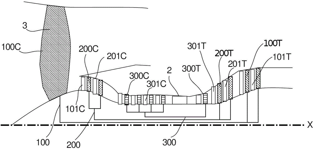
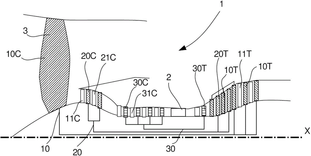
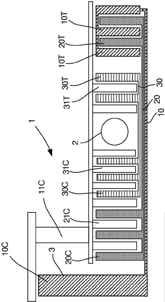
[0028] like figure 2 As shown, a turboshaft engine 1 of axis X comprises a plurality of compressor stages axially compressing the gas flow from upstream to downstream, a combustion chamber 2 and a plurality of turbine stages for recovering combustion energy. The turboshaft engine 1 includes a low-pressure rotary body 10 , an intermediate rotary body 20 and a high-pressure rotary body 30 , including compressor rotor blades 10C, 20C, 30C and turbine rotor blades 10T, 20T, 30T, respectively. In the middle of the low pressure compressor blades 10C, the turbo compressor 1 comprises upstream large fan blades 3 . Each mandrel consists of a shaft on which are mounted radially the compressor rotor blades and the turbine rotor blades. Thus, the turbine rotor blades and the compress...


PUM


Abstract

The invention relates to a gas turbine engine for propelling an aircraft, comprising: a low-pressure rotary body (10) having mobile low-pressure turbine blades (10T), an intermediary rotary body (20) having mobile intermediary turbine blades (20T), a high-pressure rotary body (30) having mobile high-pressure turbine blades (30T), a flow of air flowing through the engine from upstream to downstream. According to the invention, at least one mobile intermediary turbine blade (20T) is followed directly downstream by a mobile low-pressure turbine blade (10T) such as to straighten the flow of air deflected by the mobile intermediary turbine blade (20T).

Description

technical field [0001] This invention relates to the field of gas turbine engines used to propel aircraft. Background technique [0002] Hereinafter, the terms "upstream" and "downstream" are defined according to the flow direction of the airflow in the engine. Generally, a gas turbine engine includes, from upstream to downstream, a low-pressure compressor, a high-pressure compressor, a combustor, a high-pressure turbine, and a low-pressure turbine. To this end, the engine includes a low pressure mandrel supporting the compressor and turbine rotor blades and a high pressure mandrel supporting the compressor and turbine rotor blades. Upstream, the low-pressure compressor comprises, in a known manner, large rotor blades called "fans" by those skilled in the art. [0003] One of the ways to limit the fuel consumption of the engine is to reduce the speed of the fan blades to increase the bypass ratio of the engine, that is, the air mass of the bypass flow (air mass that is exp...

Claims


Application Information

Patent Timeline
Patent Type & Authority Applications(China)
IPC IPC(8): F02C3/067F02K3/06F02K3/072
CPCF02K3/072F02K3/06Y02T50/671F02C3/067F05D2220/323F05D2220/3213Y02T50/60F02C7/04
Inventor 飞利浦·查纳兹拉明·姆本格
Owner SN DETUDE & DE CONSTR DE MOTEURS DAVIATION S N E C M A
Why Eureka
Try Eureka