An electromagnetic mounting device for aerial bombs

An aerial bomb and mounting technology, which is applied in transportation and packaging, military equipment configuration, aircraft parts, etc., can solve the problems of large aircraft interior space, occupancy, increase radar reflection cross-sectional area, etc., and achieve the goal of reducing aerodynamic and stability performance Influence, simplification of the mounting and delivery structure, and the effect of reducing the reflection cross-sectional area

Active Publication Date: 2015-10-28
XIAN AIRCRAFT DESIGN INST OF AVIATION IND OF CHINA
View PDF5 Cites 0 Cited by
  • Summary
  • Abstract
  • Description
  • Claims
  • Application Information

AI Technical Summary

Problems solved by technology

Its disadvantages are: the mounting stress point is single, the mounting structure design is complex, the weight is heavy, and the mounting structure material requirements are high
At the same time, it must have a special ejection and delivery mechanism. The ejection and delivery mechanism has a large structure and occupies a large interior space, which has a certain impact on the aerodynamic and stability performance of the aircraft, and increases the radar reflection cross-sectional area.

Method used


Image

  • An electromagnetic mounting device for aerial bombs
  • An electromagnetic mounting device for aerial bombs
  • An electromagnetic mounting device for aerial bombs

Examples


Embodiment Construction

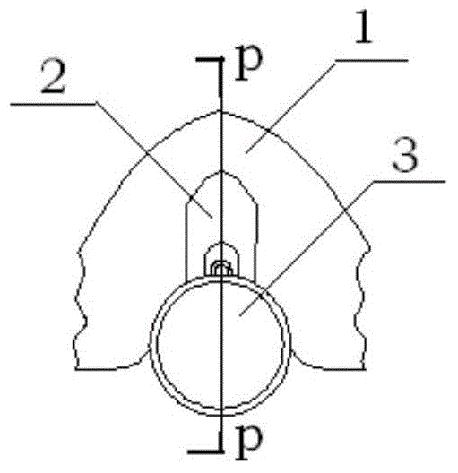
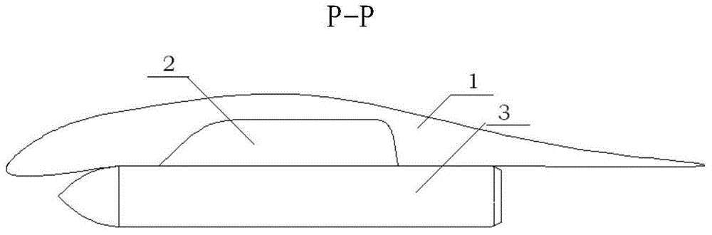
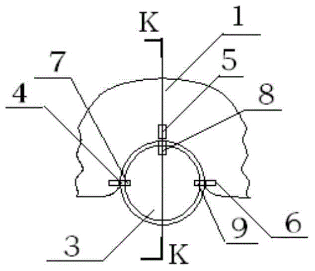
[0010] The present invention will be described in further detail below. see image 3 , 4 , an electromagnetic mounting device for aerial bombs, comprising a wing 1 of a carrier aircraft and a mounted aerial bomb 3, a semi-buried bomb bay is arranged on the lower surface of the wing 1, and the aerial bomb 3 passes through the mounting device Mounted in the semi-buried bomb bay; it is characterized in that: there are two sets of embedded bomb electromagnets on the bomb 3, and each group of bomb electromagnets consists of the first bomb electromagnet 7 and the second bomb electromagnet. The bomb electromagnet 8 and the third bomb electromagnet 9 are composed, two groups of bomb electromagnets are arranged forward and backward along the axis of the bomb 3, and the first bomb electromagnet 7 to the third bomb electromagnet 9 are arranged along the semicircle of the bomb 3 Evenly distributed around the week; there are two groups of bomb electromagnets on the inner surface of the s...


PUM


Abstract

The invention provides a bomb electromagnetic mounting device, belongs to the bomb mounting technology, and relates to an improvement of an aircraft bomb mounting structure. The bomb electromagnetic mounting device is characterized in that two groups of embedded bomb electromagnets are arranged on a bomb (3), wherein each group of embedded bomb electromagnets includes the first bomb electromagnet (7), the second bomb electromagnet (8) and the third bomb electromagnet (9). Two groups of bomb hanging electromagnets are arranged on the inner surface of a half-buried bomb hanging cabin, wherein the axial position of the first group of bomb hanging electromagnets corresponds to that of the first group of embedded bomb electromagnets, and the axial position of the second group of bomb hanging electromagnets corresponds to that of the second group of embedded bomb electromagnets. According to the bomb electromagnetic mounting device, mounting force bearing points are added, a mounting structure and a releasing structure are simplified, the weight of the mounting structure is reduced, the requirement for materials of the mounting structure is lowered, occupied space inside an aircraft is reduced, influence on pneumatic and steady performance of the aircraft is reduced, and the sectional area of radar reflection is reduced.

Description

technical field [0001] The invention belongs to the aerial bomb mounting technology and relates to the improvement of the aircraft aerial bomb mounting structure. Background technique [0002] For a current semi-buried aerial bomb mounting structure, see figure 1 and figure 2 , it is composed of the wing 1 pylon unit 2 of the carrier aircraft and the mounted aerial bomb 3 . A semi-buried bomb bay is arranged on the lower surface of the wing 1, and the aerial bomb 3 is mounted in the semi-buried bomb bay by a mounting device. The upper end of the pylon unit 2 is connected with the load-bearing member of the wing 1 as a whole, and the lower end of the pylon unit 2 is connected with the hanging point of the aerial bomb 3 . Its disadvantages are: the mounting force point is single, the mounting structure design is complex, the weight is large, and the mounting structure material requirements are high. At the same time, it must have a special ejection and delivery mechanism....

Claims


Application Information

Patent Timeline
Patent Type & Authority Patents(China)
IPC IPC(8): B64D7/00
Inventor 蒋汉杰任江涛赵天娇商立英
Owner XIAN AIRCRAFT DESIGN INST OF AVIATION IND OF CHINA
Why Eureka
Try Eureka