Pilot large-flow load control valve using displacement and force feedback principle

A technology of load control and force feedback, which is applied in the direction of fluid pressure actuators, servo motor components, mechanical equipment, etc., can solve the problems of load speed jitter, large stability margin of the main valve core, poor load speed control effect, etc., to achieve Stable load speed control, improved stability, and compact overall structure

Active Publication Date: 2014-02-12
ZHEJIANG UNIV
View PDF7 Cites 10 Cited by
  • Summary
  • Abstract
  • Description
  • Claims
  • Application Information

AI Technical Summary

Problems solved by technology

[0005] In order to overcome the shortcomings of the load control valve or balance valve in the hydraulic system that exceeds the load in the background technology, the load speed control effect is poor, and the load speed vibration is easy to occur. Load control valve, the valve not only has good speed control characteristics, but also has a large stability margin of the main spool, which effectively suppresses the vibration of the load speed, and is suitable for hydraulic systems with overrunning loads

Method used


Image

  • Pilot large-flow load control valve using displacement and force feedback principle
  • Pilot large-flow load control valve using displacement and force feedback principle
  • Pilot large-flow load control valve using displacement and force feedback principle

Examples


Embodiment Construction

[0021] The present invention will be further described below in conjunction with drawings and embodiments.

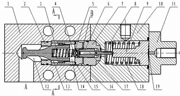
[0022] Such as figure 1 As shown, the present invention includes a main valve body 1, a main valve sleeve 2, a main valve core 3, a feedback spring 4, a load pressure compensation damper 5, a pilot valve core 6, a pilot valve sleeve 7, a control spring 8, a control piston 9 and a pilot Valve body 10 and end cover 11.

[0023] Such as figure 1 As shown, the main valve sleeve 2 is installed in the cylindrical hole of the main valve body 1, the oil return cavity 12 is formed between the bottom of the main valve sleeve 2 and the hole of the main valve body 1, and the small end of the main valve core 3 passes through the main valve sleeve 2 and is located at In the oil return chamber 12, the large end of the main valve core 3 is in sliding fit with the inner hole of the main valve sleeve 2, one end of the pilot valve sleeve 7 is installed in the cylindrical hole of the mai...


PUM


Abstract

The invention discloses a pilot large-flow load control valve using a displacement and force feedback principle. The valve comprises a main valve body, a main valve sleeve, a main valve element, a feedback spring, a load pressure compensation damper, a pilot valve element, a pilot valve sleeve, a control spring, a control piston, a pilot valve body and an end cap. An oil return cavity, a load cavity, a control-sensitive cavity, a high-pressure cavity, an inner containing cavity of the pilot valve element, an oil drainage cavity and a channel communicating the load cavity and the high-pressure cavity are formed in the load control valve. The load control valve can control the load discharging speed of a hydraulic system with an exceeding load, and can effectively prevent the load speed fluctuation problem of a traditional load control valve. A vibration damping tail of the head portion of the main valve element offsets hydraulic force influences borne by the main valve element. The speed control function in load discharging and the one-way valve function in load rising are integrated on the main valve element so that the whole structure of the load control valve can be compact. The pilot valve element and the pilot valve sleeve are designed in a matched mode, so that the load control valve has a quick closing function.

Description

technical field [0001] The invention relates to a hydraulic control element, in particular to a pilot large flow load control valve applying the principle of displacement-force feedback. Background technique [0002] In hydraulic system applications such as hoisting machinery, hydraulic winches, and construction machinery, it often occurs that the direction of the load force is consistent with the direction of the load's motion. This load is called an overrunning load (negative load). The hydraulic system that bears the excess load needs a special control valve to control the flow of hydraulic oil flowing from the load back to the oil source. When the load flow is large, this kind of control valve is generally called a load control valve or a balance valve. [0003] However, due to the high load pressure and complex load conditions, the flow control characteristics of the load control valve directly determine the speed control characteristics and speed stability of the hydra...

Claims


Application Information

Patent Timeline
Patent Type & Authority Applications(China)
IPC IPC(8): F15B13/02
Inventor 谢海波刘建彬杨华勇
Owner ZHEJIANG UNIV
Why Eureka
Try Eureka