
Electronic light emitting device simulating true fire and electronic candle lamp simulating true fire

A light-emitting device and a technology for simulating real fire, which is applied to the parts of lighting devices, electric light sources, electric light sources, etc., can solve the problems of not being realistic enough, requiring many parts, and difficult to guarantee reliability, etc., and achieve realistic and easy simulation effects. Manufacture and assembly, easy to market acceptance effect

Inactive Publication Date: 2014-02-12
黄立伟
View PDF5 Cites 10 Cited by
  • Summary
  • Abstract
  • Description
  • Claims
  • Application Information

AI Technical Summary

Problems solved by technology

But in actual application, because the flame sheet is always swinging constantly under the action of electromagnetic force, it is obvious that the effect of man-made flame swinging is not realistic enough compared with the natural swinging effect, and the structure of the electronic light-emitting device is relatively complicated. , more parts are required, the production is complicated, the cost is also high, and the reliability is difficult to guarantee after long-term use

Method used


Image

  • Electronic light emitting device simulating true fire and electronic candle lamp simulating true fire
  • Electronic light emitting device simulating true fire and electronic candle lamp simulating true fire
  • Electronic light emitting device simulating true fire and electronic candle lamp simulating true fire

Examples


Embodiment Construction

[0027] In order to facilitate the understanding of those skilled in the art, the present invention will be further described in detail below with reference to the drawings and embodiments.

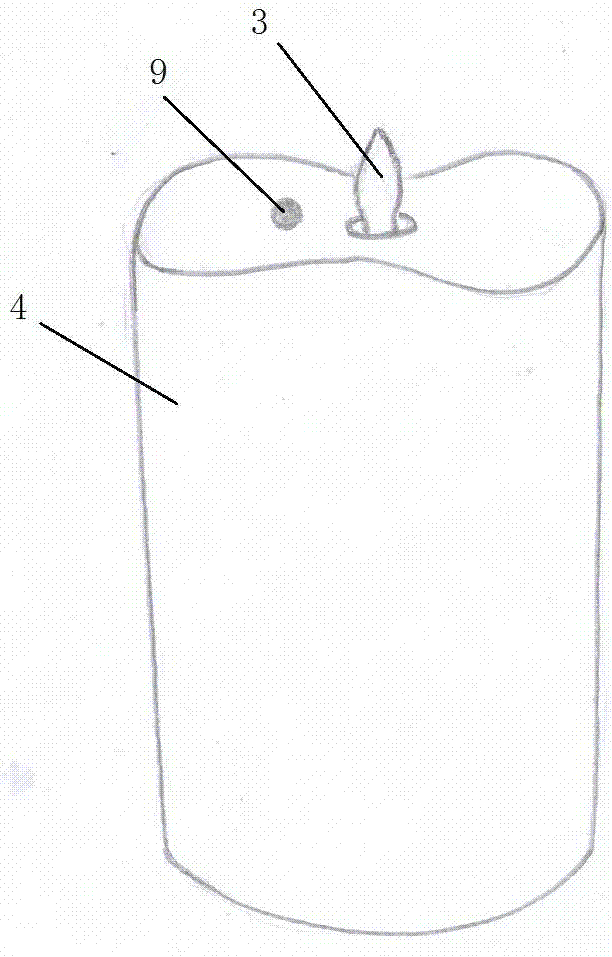
[0028] The electronic light-emitting device simulating a real fire disclosed in this embodiment can be applied to various electronic decorative objects, such as electronic candles, electronic oil lamps, etc., and has a wide range of applications.

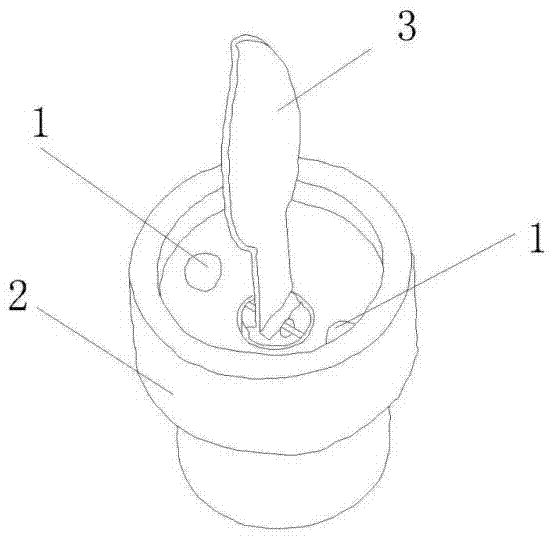
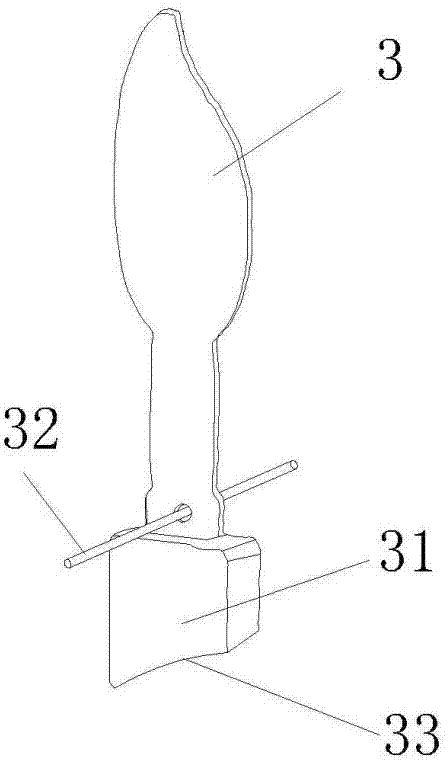
[0029] Specific as attached figure 1 , 2 shown. The electronic light-emitting device for simulating real fire disclosed in this embodiment includes two light-emitting diodes 1 as light-emitting components, a mount 2 for installing the light-emitting diodes, and a control circuit for controlling the work of the light-emitting diodes 1. A flame is installed upward on the upper end of the mount 2. Sheet 3, two light-emitting diodes 1 are respectively located in the mounting seat 2 on the front and rear sides of flame sheet 3, so that light is pro...


PUM


Abstract

Provided is an electronic candle lamp simulating true fire. The electronic candle lamp simulating true fire comprises a candle outer shell and a light emitting device installed in the candle outer shell. The light emitting device comprises at least one light emitting component, an installation base for installation of the light emitting components, and a control circuit for controlling the light emitting components to work, wherein a flame piece which can shake flexibly is vertically installed at the upper end of the installation base, the flame piece is in a flame shape, light emitted by the light emitting components is aslant projected on the flame piece from bottom to top, an exposed light image on the flame piece is in a shape of a flame which is high in brightness of the lower middle portion and gradually darkens upwards, and an atomization drive assembly which can atomize perfume and drive the flame piece to swing is installed in the candle outer shell and located below the flame piece. The image on the flame piece flickers, twinkles, swings naturally and is free of the feeling of manual drive, the simulation effect of the flame is vivid, interestingness and ornamental value are achieved, and the electronic candle lamp simulating true fire is simple in structure, more stable and reliable and easy to manufacture and assemble, has a good visual effect and can give out fragrance.

Description

technical field [0001] The present invention relates to improved techniques for simulating electronic light emitting devices. Background technique [0002] In daily life, various electronic light-emitting devices are widely used in toys, home decoration, gifts and religious ceremonies. For example, the simulated electronic candle lamp is one of the most widely used electronic light-emitting devices. The light-emitting part of this type of electronic light-emitting device tries to simulate the light-emitting form of a candle or kerosene lamp, and simulates the effects of flickering, flickering, etc. The gap is large, and the visual experience is unreal. [0003] Patent No. 20101021114028, titled "Electronic light-emitting device for simulating real fire and its method for simulating real fire", discloses an electronic light-emitting device with better effect of simulating flame. The projection on the film is a flame swinging. But in actual application, because the flam...

Claims


Application Information

Patent Timeline
IPC IPC(8): F21S10/04F21V14/00F21V33/00H05B37/02
Inventor 黄立伟
Owner 黄立伟
Learn More