
System for Measuring Power Factor and Normalized Integral Method Using the System

A technology of power factor and proportional integral, which is applied in the direction of electric power measurement through current/voltage, can solve the problems of voltage clutter and high-order harmonics, and cannot obtain high-precision measurement, etc., and achieves easy implementation and simple structure , low cost effect

Active Publication Date: 2016-04-06
思锐电气有限公司
View PDF5 Cites 0 Cited by
  • Summary
  • Abstract
  • Description
  • Claims
  • Application Information

AI Technical Summary

Problems solved by technology

This method can be used for control, but it is easily affected by voltage clutter and high-order harmonics, and cannot obtain high-precision measurement

Method used


Image

  • System for Measuring Power Factor and Normalized Integral Method Using the System
  • System for Measuring Power Factor and Normalized Integral Method Using the System
  • System for Measuring Power Factor and Normalized Integral Method Using the System

Examples


Embodiment Construction

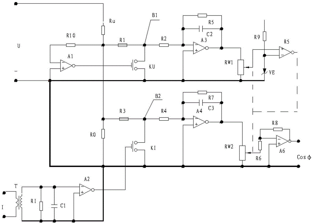
[0029] Such as figure 1 As shown, the system for measuring power factor of the present invention includes a sinusoidal voltage input from the positive terminal of U, which is divided by resistor Ru and resistor R0 as a voltage signal. The voltage signal is divided into three paths:

[0030] The first voltage signal is connected to the negative input pole of the comparison amplifier A1 through the resistor R10, and the output stage of the comparison amplifier A1 is connected to the electronic switch KU;

[0031] The second voltage signal is connected to the negative input terminal of the proportional integral amplifier A3 through the resistor R1 and the resistor R2 in turn. The negative input terminal of the proportional integral amplifier A3 is connected to the resistor R5 and the capacitor C2. The other end of the resistor R5 and the capacitor C2 is connected to the proportional integral amplifier A3. At the output end, the output end of the proportional integral amplifier A3 is co...


PUM


Abstract

The invention relates to a power factor measurement system and a normalizing integration method with the power factor measurement system used. According to the power factor measurement system, sinusoidal voltages are input from a U-end positive electrode, the sinusoidal voltages are divided through a resistor Ru and a resistor R0 to serve as voltage signals, and the voltage signals are divided into three routes. The first route of voltage signals are connected with the negative input stage of a comparison amplifier A1 through a resistor R10, and the output stage of the comparison amplifier A1 is connected with an electronic switch KU. The second route of voltage signals are connected with the negative input end of a proportion integration amplifier A3 sequentially through a resistor A1 and a resistor A2. The third route of voltage signals are connected with the negative input end of a proportion integration amplifier A4 sequentially through a resistor R3 and a resistor R4. By means of the power factor measurement system and the normalizing integration method, high-precision and stable measurement results can be obtained, and if the sampling width of current signals is shortened, a certain specific harmonic wave can further be eliminated.

Description

Technical field [0001] The invention relates to a system for measuring power factor and an integration method adopting the system. Background technique [0002] In the prior art, there are generally two methods for power factor measurement. One is to test with an electric meter. This method can only be read directly and cannot be turned into an electrical signal for control; the other is to first measure the difference between current and voltage. Phase, and then use the microcontroller to calculate the power factor value. This method can be used for control, but it is susceptible to voltage clutter and higher harmonics and cannot obtain high-precision measurement. Summary of the invention [0003] The technical effect of the present invention can overcome the above-mentioned defects and provide a system for measuring power factor with simple structure, low cost and easy realization. [0004] In order to achieve the above objective, the present invention adopts the following techn...

Claims


Application Information

Patent Timeline
Patent Type & Authority Patents(China)
IPC IPC(8): G01R21/06
Inventor 薄焕林张云帆
Owner 思锐电气有限公司
Learn More