Projector optical machine with automatic focusing function

A projector optical-mechanical and auto-focusing technology, applied in the field of optical-mechanical focusing, can solve problems such as excessive size, slight lens shift, and trouble.

Inactive Publication Date: 2014-02-12
HOTUS TECH CO LTD
View PDF7 Cites 6 Cited by
  • Summary
  • Abstract
  • Description
  • Claims
  • Application Information

AI Technical Summary

Problems solved by technology

Because the projection lens is under the influence of its own gravity, even if the projector keeps a fixed position, the internal lens will shift slightly after a long time, so that the projection picture becomes blurred, and the focus must be manually adjusted again to make the picture clear, this is troublesome
Especially when the projector is hung from a high place such as the ceiling, the user will often climb to a high place to manually adjust the focus, which is inconvenient to use and has the risk of falling
[0003] like figure 1 In the shown prior art, the motor gear assembly 100a used in small products such as eyelash brushes includes a shaft sleeve 1 and a gear tooth portion 2, wherein the diameter of the shaft sleeve 1 is about 3.6 mm, and the gear tooth portion 2 and the shaft The distance of set 1 is about 2.7 mm, which is too large, and the output speed of the gear is relatively fast, so it is not suitable for the field of finely adjusting the optical-mechanical focal length, and the scope of use has certain limitations.

Method used


Image

  • Projector optical machine with automatic focusing function
  • Projector optical machine with automatic focusing function
  • Projector optical machine with automatic focusing function

Examples


Embodiment Construction

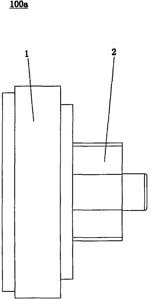
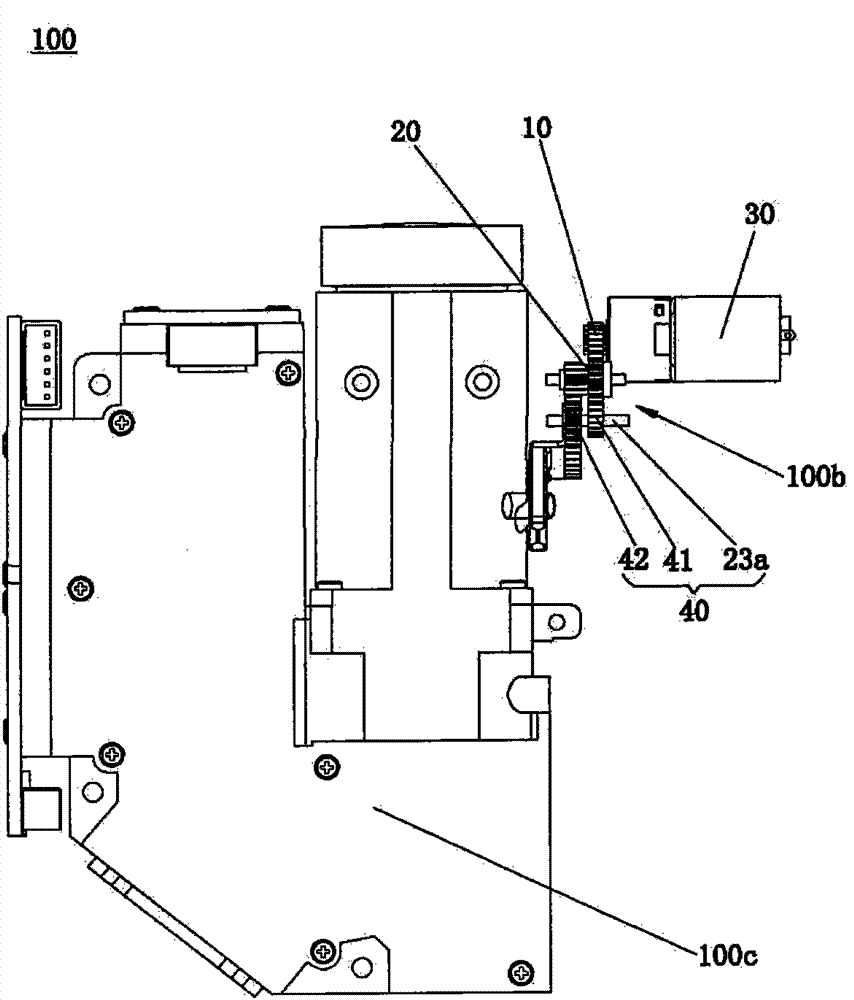
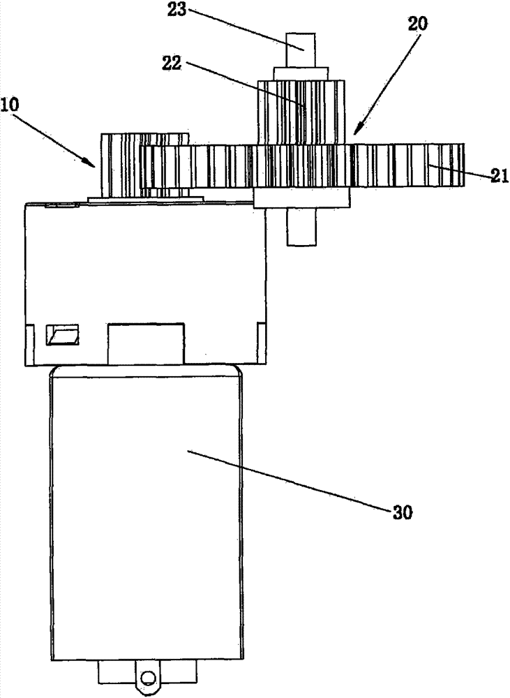
[0018] Embodiments of the present invention will now be described with reference to the drawings, in which like reference numerals represent like elements. As mentioned above, such as figure 2 , 3 As shown in , 4, the projector optical machine 100 with automatic focus function provided by the present invention includes a focus motor gear assembly 100b, and the focus motor gear assembly 100b includes: a driving gear 10, a first driven gear assembly 20 and The motor 30 that drives the driving gear 10 to rotate, the driving gear 10 drives the first driven gear assembly 20 to rotate, as Figure 4 As shown, the driving gear 10 includes a first gear tooth portion 11 and a shaft sleeve 12 integrally structured with the first gear tooth portion 11, and the output shaft (not shown) of the motor 30 passes through the shaft sleeve The side where 12 is located penetrates into the shaft hole (not shown in the figure) of the driving gear 10 to be connected and installed with the driving ...


PUM


Abstract

The invention discloses a projector optical machine with the automatic focusing function. The projector optical machine with the automatic focusing function comprises a focusing motor gear assembly, an optical machine body and a main control system. The focusing motor gear assembly comprises a drive gear, a first driven gear assembly, a second driven gear assembly and a motor driving the drive gear to rotate. The drive gear drives the first driven gear assembly and the second driven gear assembly to rotate, and comprises a first gear tooth part and a shaft sleeve integrated with the first gear tooth part. An output shaft of the motor penetrates through a shaft hole of the drive gear from one side where the shaft sleeve is located, then the output shaft of the motor is connected and installed with the drive gear, the outer diameter of the shaft sleeve is 3.6mm, the length of the first gear tooth part is 2.7mm and the outer diameter of the motor is 10mm. The optical machine body is used for installation of the focusing motor gear assembly. The main control system is electrically connected with the motor and used for controlling the motor to rotate to carry out focusing on the optical machine body. The projector optical machine with the automatic focusing function can achieve the automatic focusing function, and is convenient and fast to use, and safe.

Description

technical field [0001] The invention relates to the field of optical-mechanical focusing on a projector, in particular to an optical-mechanical projector with an automatic focusing function that can realize an automatic focusing function regardless of whether the projector is placed at a distance or a high place, which is convenient, fast and safe. Background technique [0002] Projectors on the market now use the principle of manual focus to adjust the focal length according to the change of the distance, so as to realize the function of clear image of the projector. Because the projection lens is under the influence of its own gravity, even if the projector keeps a fixed position, the internal lens will shift slightly after a long time, so that the projection picture becomes blurred, and the focus must be manually adjusted again to make the picture Clear, this is very troublesome. Especially if the projector is hung from a high place such as the ceiling, the user will oft...

Claims


Application Information

Patent Timeline
Patent Type & Authority Applications(China)
IPC IPC(8): G03B21/53G02B7/09
Inventor 肖文海
Owner HOTUS TECH CO LTD
Why Eureka
Try Eureka