A cell analysis chip and its cell fluorescence detection system and detection method

An analysis chip and fluorescence detection technology, which is applied in the field of cell analysis, can solve the problems of low efficiency, achieve the effects of reducing time, simplifying the overall design, and improving detection efficiency

Active Publication Date: 2021-02-19
GUANGDONG UNIV OF TECH
View PDF6 Cites 0 Cited by
  • Summary
  • Abstract
  • Description
  • Claims
  • Application Information

AI Technical Summary

Problems solved by technology

However, the fluorescence detection systems in the prior art are often only satisfied with the single-color fluorescence detection of samples, and are powerless for multi-color fluorescence-labeled samples.
In addition, although the existing multi-channel optical detection devices can meet the requirements of multi-color fluorescence detection, they often have certain deficiencies, resulting in low efficiency when working.

Method used


Image

  • A cell analysis chip and its cell fluorescence detection system and detection method
  • A cell analysis chip and its cell fluorescence detection system and detection method
  • A cell analysis chip and its cell fluorescence detection system and detection method

Examples


Embodiment 1

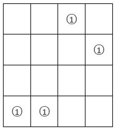
[0038] Such as figure 1 and figure 2 As shown, a cell analysis chip, which includes a first reaction pool 1, a second reaction pool 2, a flow channel 3 and a buffer pool 4, the first reaction pool 1 and the second reaction pool 2 communicate with the One end of the flow channel 3 is connected, and the buffer pool 4 is connected to the other end of the flow channel 3. The flow channel 3 is in a serpentine reciprocating shape, and the adjacent two reciprocating sections of the serpentine reciprocating flow channel 3 are provided with A plurality of well structures 5 whose two ends are respectively communicated with the two adjacent reciprocating sections.

[0039] Such as figure 1 and figure 2 As shown, the end of the well structure 5 close to the first reaction cell 1 is the entrance of the well structure 5, the end of the well structure 5 close to the buffer pool 4 is the exit of the well structure 5, and the diameter of the well structure 5 is R is 1.2-1.5 times the cell ...

Embodiment 2

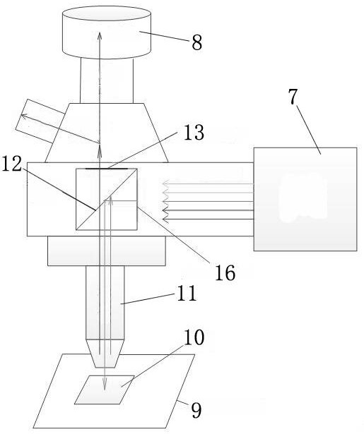
[0044] Such as image 3 As shown, a cell fluorescence detection system, which includes a workstation 6, an excitation light source 7 electrically connected to the workstation 6, a CCD 8 and a three-dimensional mobile platform 9, the three-dimensional mobile platform 9 is provided with a microfluidic chip 10, The microfluidic chip 10 is the cell analysis chip described in Example 1, and the microfluidic chip 10 is provided with an objective lens 11, a half mirror 12 and a first light adjusting device in sequence from bottom to top. The CCD8 is arranged above the first light rectifying device, and the position of the excitation light source 7 satisfies that the light emitted by the excitation light source 7 is reflected by the half mirror 12, and then focused on the microfluidic device through the objective lens 11. On the chip 10 , a second light adjustment device is arranged between the excitation light source 7 and the half mirror 12 .

[0045] Such as image 3 As shown, th...

Embodiment 3

[0049] A cell fluorescence detection method, wherein, comprising the steps of:

[0050] S1. Close the conduit connecting the first reaction tank 1 and the flow channel 3, continuously inject mineral oil into the second reaction tank 2, and stop injecting mineral oil into the second reaction tank 2 after the inside of the flow channel 3 is filled with mineral oil, Stand still for a certain period of time until no droplet is produced at the end where the flow channel 3 is connected to the buffer pool 4;

[0051] S2. Mix different antibodies labeled with different fluorescent dyes with the cell suspension evenly, then inject the cell suspension into the first reaction pool 1, stop the injection after the first reaction pool 1 is filled with the cell suspension, and then slowly Open the conduit connecting the first reaction pool 1 and the flow channel 3, and let it stand for a certain period of time to adjust the pressure difference;

[0052] S3. Continue to inject cell suspensio...


PUM


Abstract

The invention provides a cell analysis chip. A cell analysis chip, which includes a first reaction pool, a second reaction pool, a flow channel and a buffer pool, the first reaction pool and the second reaction pool communicate with one end of the flow channel through a conduit, and the buffer The pool is connected to the other end of the flow channel, and the flow channel is in a serpentine reciprocating shape, and there are several traps between the two adjacent reciprocating sections of the serpentine reciprocating flow channel. structure. The present invention also provides a fluorescence detection system and detection method with the above-mentioned cell analysis chip. The invention can greatly improve the detection efficiency, can meet the requirement of multi-color fluorescence detection, has a simple overall system design, and improves the detection sensitivity and working efficiency of the whole system.

Description

technical field [0001] The invention relates to the technical field of cell analysis, and more specifically, to a cell analysis chip, a cell fluorescence detection system and a detection method thereof. Background technique [0002] With the development of modern biomedical technology and the abuse of antibiotics by humans, traditional group sample detection covers up a lot of important information, and even erroneous results may appear. It is particularly important to detect and analyze a single sample. Well complete the sample testing and analysis. [0003] Lab on a chip, also referred to as a microfluidic analysis chip, integrates the basic operating units of sample preparation, reaction, separation, and detection in the biological and chemical medical analysis process into a micron-scale chip to automatically complete the analysis The whole process. Due to its great potential in the fields of biology, chemistry, and medicine, it has developed into a new research field ...

Claims


Application Information

Patent Timeline
Patent Type & Authority Patents(China)
IPC IPC(8): G01N21/64G01N21/01
CPCG01N21/01G01N21/6402G01N21/6486
Inventor 邓宇王文兵郭钟宁
Owner GUANGDONG UNIV OF TECH
Why Eureka
Try Eureka