

Driver IC, mounting board, display unit, and projection display unit
A driver and mounting board technology, used in instruments, static indicators, etc., can solve the problems of complex wiring layout and increased wiring area occupancy rate, and achieve the effect of reducing area occupancy rate and simplifying wiring layout.
- Summary
- Abstract
- Description
- Claims
- Application Information
AI Technical Summary
Problems solved by technology
Method used
Image

Examples
no. 1 approach
[0034] 1. The first embodiment (display unit)
[0035] 2. Modified example of the first embodiment (display unit)
[0036] 3. The second embodiment (projection display unit)
[0037] 4. The third embodiment (projection display unit)
[0038] 1. The first implementation plan
[0039] [structure]
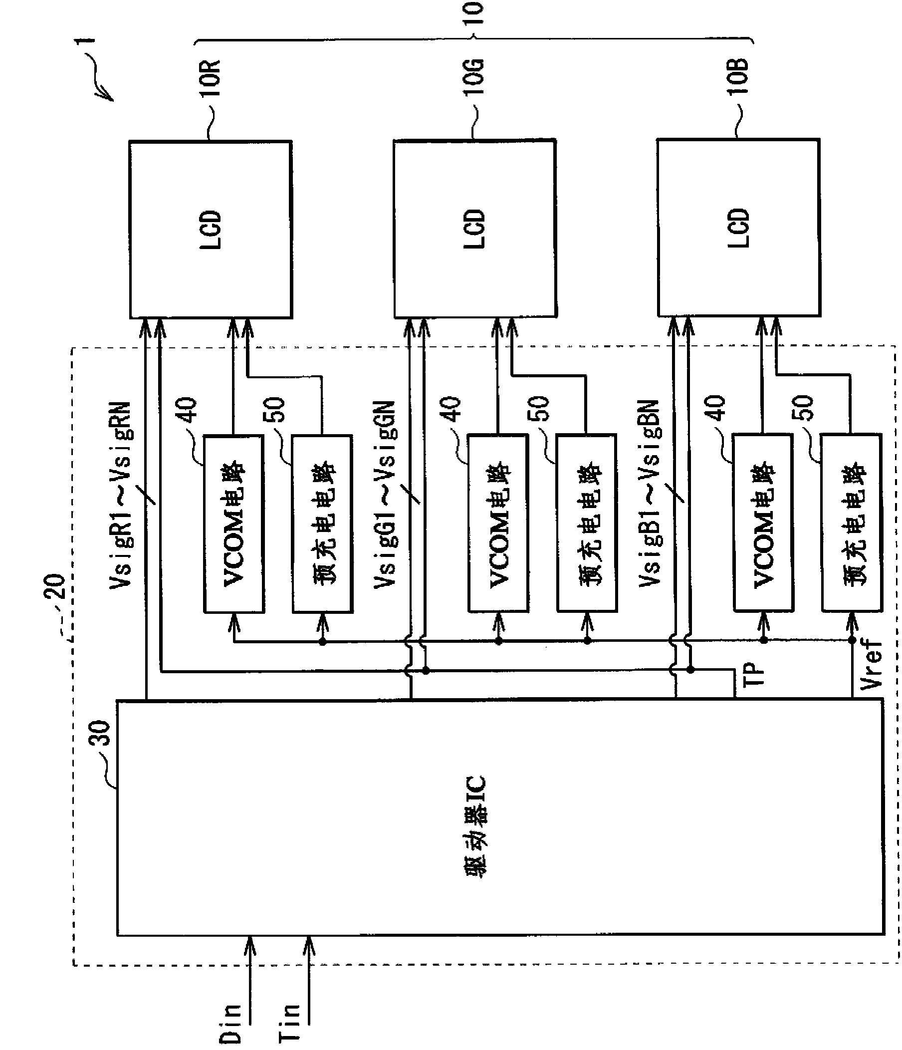
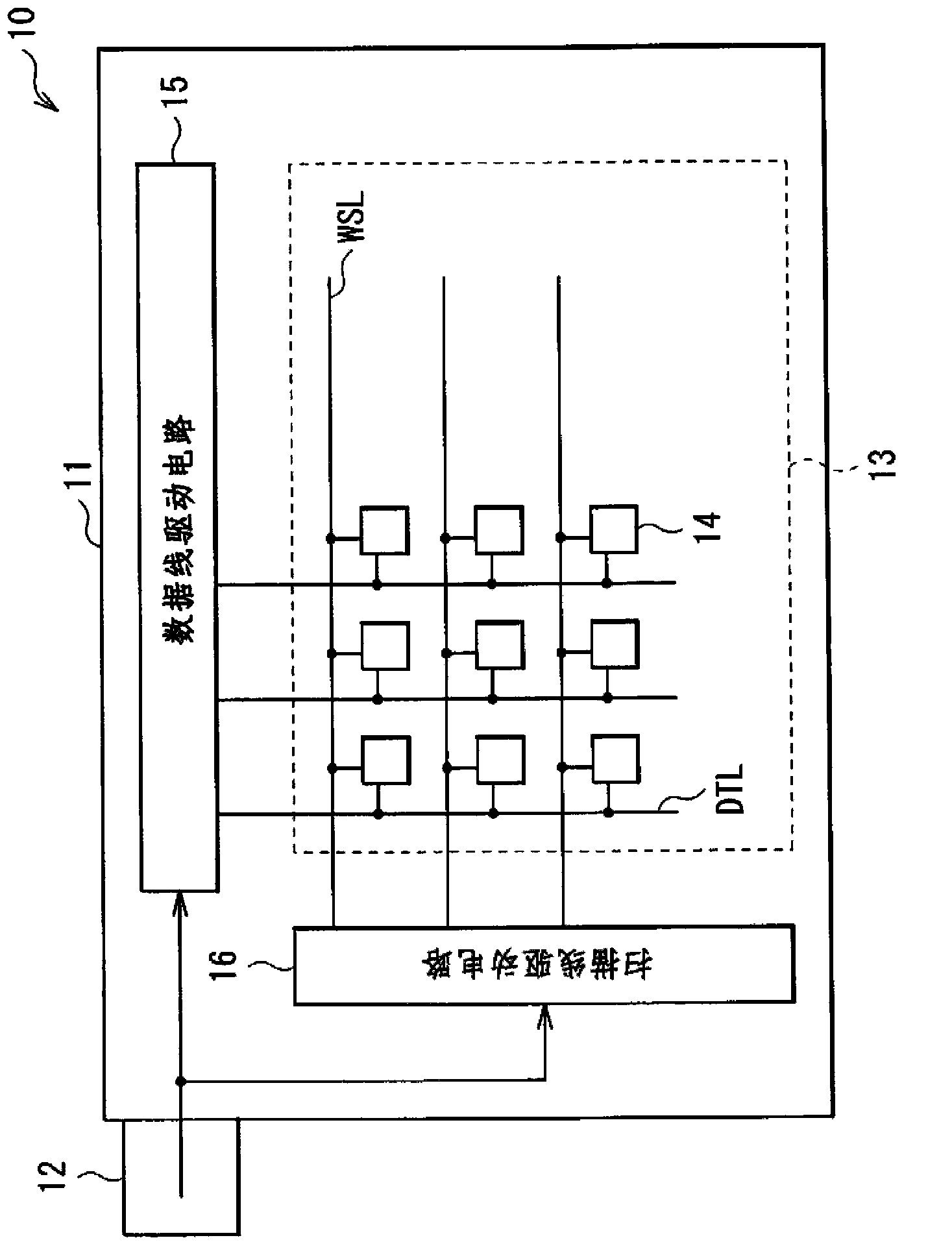
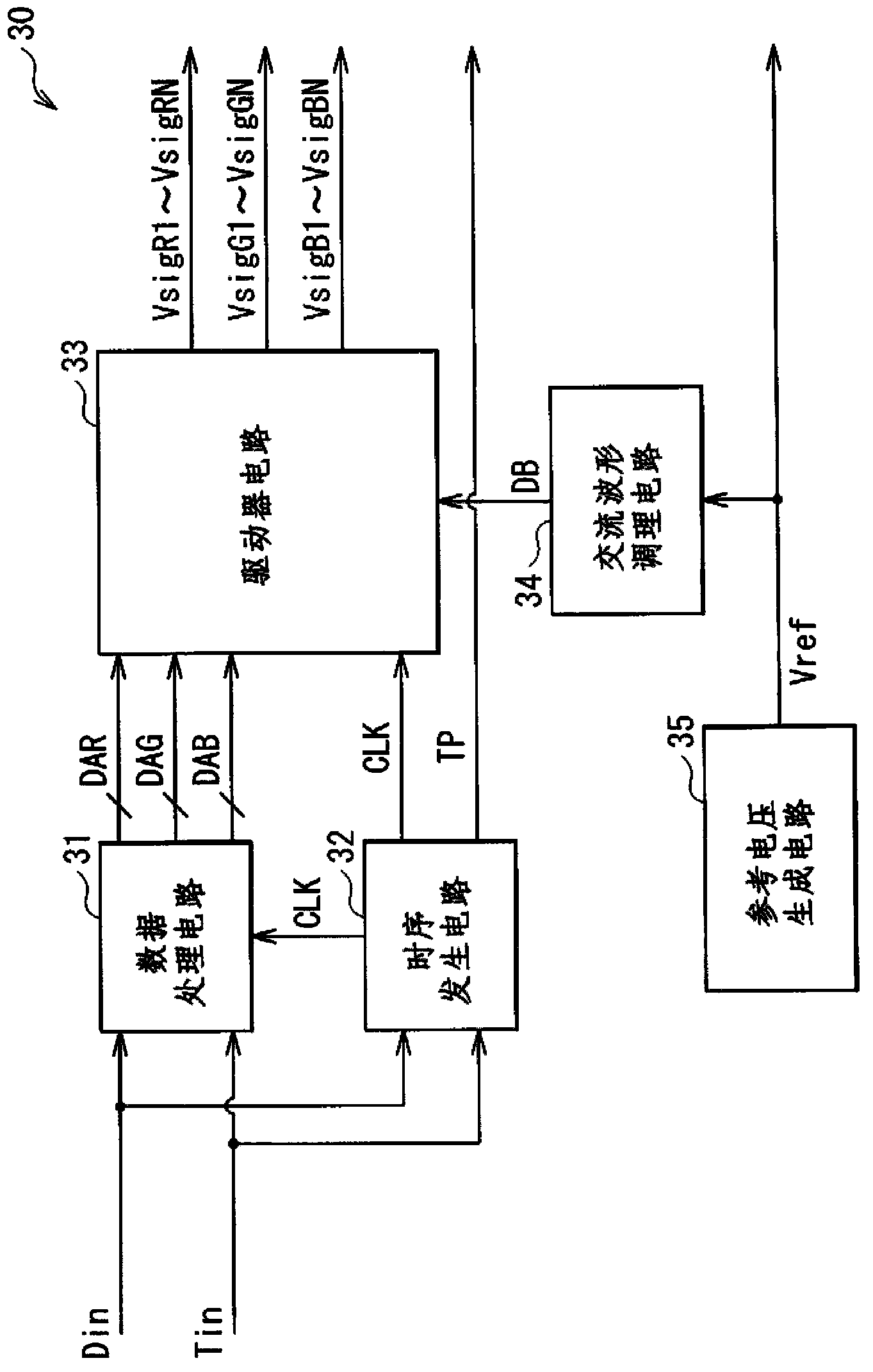
[0040] figure 1A schematic configuration of the display unit 1 of the first embodiment of the present invention is illustrated. The display unit 1 can be adapted as a light valve of a three-panel projector (projection display unit). For example, the display unit 1 may include liquid crystal display (LCD) panels 10R, 10G, and 10B and a driving circuit 20 . Note that, if the liquid crystal display panels 10R, 10G, and 10B are each of the transmissive type, the display unit 1 includes a light source (not shown) located on the back of each of the liquid crystal display panels 10R, 10G, and 10B.
[0041] Hereinafter, the term "liquid crystal display panel 10" is used as a general te...
Deformed example 1
[0085] Figure 11 The configuration of the display unit 1 corresponding to Modification 1 of the first embodiment is illustrated. The display unit 1 of Modification 1 is configured by modifying the display unit 1 of the first embodiment such that the display unit 1 further includes a temperature detection circuit 60 for detecting the temperature of the mounting board 20A. The temperature detection circuit 60 corresponds to a specific example of the "first detection circuit" of one embodiment of the present invention, but this example is not limitative.
[0086] In Modification 1, the mounting board 20A further includes the temperature detection circuit 60 on the wiring substrate 21 . In this configuration, for example, as Figure 12 As shown, the amplifying circuit 45 may be composed of a video signal amplifier 46 and an output control circuit 47, the video signal amplifier 46 drives the liquid crystal display panel 10, and the output control circuit 47 outputs the control s...
Deformed example 2
[0090] Figure 16 The configuration of the display unit 1 corresponding to Modification 2 of the first embodiment is illustrated. The display unit 1 of Modification 2 is constituted by modifying the display unit 1 of the first embodiment such that the display unit 1 further includes a detection mechanism for detecting the difference between the driver IC 30 and the liquid crystal display panel 10. electrical connection between them. For example, if Figure 16 As shown, such a detection mechanism may include an output control circuit 47, a wire 29 connected to an input terminal (not shown) of the output control circuit 47, and an upper wire connected to the wire 29 at a point close to the output control circuit 47. pull circuit 48.
[0091] The wiring 29 extends from the input terminal of the output control circuit 47 to the liquid crystal display panel 10 via the FPC 12 , and returns from the liquid crystal display panel 10 to the wiring board 21 via the FPC 12 . The wirin...
PUM
 Abstract
Description
Claims
Application Information