X-ray detector and method for operating same

An X-ray, detector technology, applied in the field of running this X-ray detector, can solve problems such as misorientation, image quality degradation, etc.

Inactive Publication Date: 2014-02-19
SIEMENS HEALTHCARE GMBH
View PDF5 Cites 7 Cited by
  • Summary
  • Abstract
  • Description
  • Claims
  • Application Information

AI Technical Summary

Problems solved by technology

[0005] In this case, a change in the focus position determines a change in the relative positioning of the x-ray focus and the x-ray detector as well as the scattered radiation collimator, which almost leads to a mutual misalignment of the x-ray radiation source and the x-ray radiation detector and thus to degraded image quality achievable with this device

Method used


Image

  • X-ray detector and method for operating same
  • X-ray detector and method for operating same
  • X-ray detector and method for operating same

Examples


Embodiment Construction

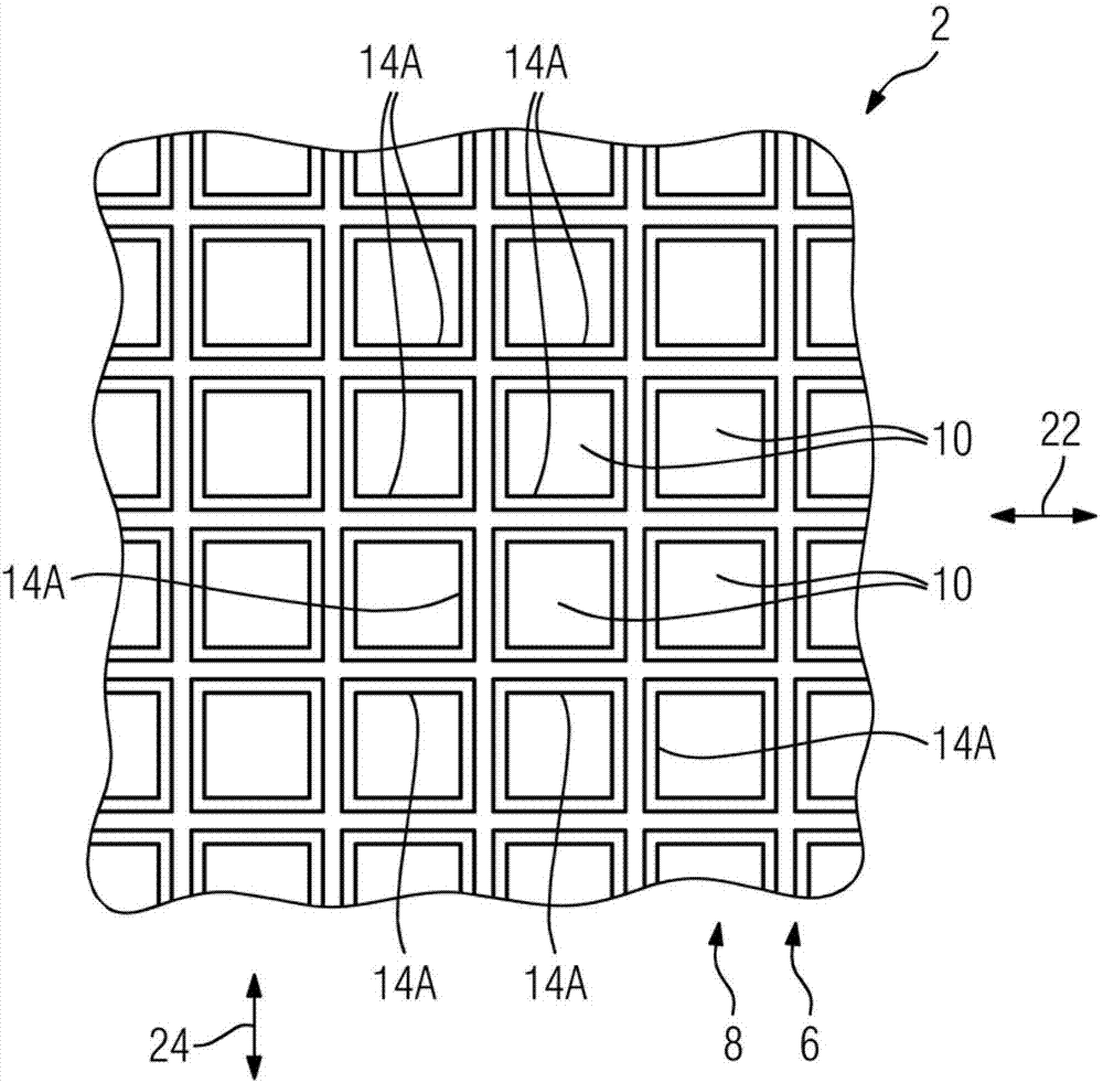
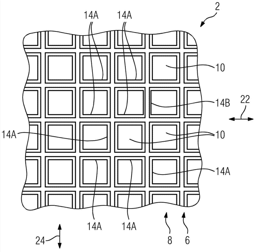
[0030] Mutually corresponding parts are respectively provided with the same reference numerals in all figures.

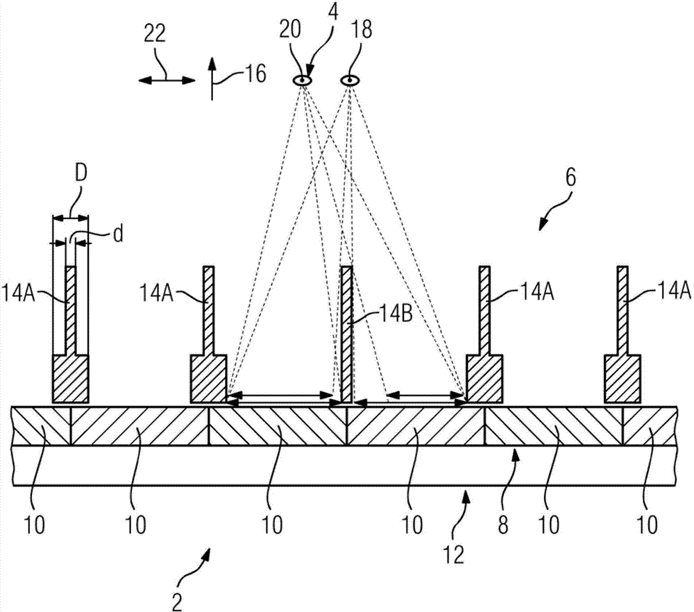
[0031] The x-ray detector 2 described by way of example below is also, for example, the x-ray radiation source 4 of a computed tomography system for examining objects or patients by imaging methods according to known principles. In this computed tomography device, as in figure 1 As shown in , the X-ray detector 2 and the X-ray radiation source 4 are arranged opposite to each other, and for examining the object or the patient it is placed in an unillustrated space between the X-ray detector 2 and the X-ray radiation source 4 Check the table.

[0032] The generation of X-ray radiation takes place by means of an X-ray tube not depicted, wherein the generation of X-ray radiation is limited to a relatively small area of ​​the anode, the so-called focal spot. This focal spot acts very approximately as at figure 1 The point-shaped X-ray radiation source 4 represented by...


PUM


Abstract

An X-ray detector (2) is disclosed, in particular for a medical imaging device (2, 4). The X-ray detector includes an anti-scatter grid (6) made up of walls (4), a measuring layer (8) including a regular arrangement of measuring cells (10), and an evaluation unit (12). The anti-scatter grid (6) covers the measuring layer (8) and is aligned toward a specific focal point (18). The evaluation unit (12) is configured to determine a focal position (20) of an X-ray source (4) relative to the focal point (18) based on a local intensity difference of X-rays striking the measuring layer (8).

Description

technical field [0001] The invention relates to an x-ray detector, in particular for imaging medical devices, comprising a scattered radiation collimator constructed from walls, a measuring layer with regularly arranged measuring cells and an analyzing unit. Furthermore, the invention relates to a method for operating such an x-ray detector. Background technique [0002] If X-ray radiation is used in imaging methods, this X-ray radiation is typically generated in an X-ray tube and radiates here from a relatively small surface on the anode, which can usually be well approximated as a point-like The source of X-ray radiation, and typically referred to as the X-ray focus. Furthermore, for carrying out the imaging method, x-ray radiation detectors are frequently used, which are formed from regularly arranged detector cells or detector pixels. [0003] When examining an object or a patient by a structure comprising such an x-ray radiation source and an x-ray detector, the atten...

Claims


Application Information

Patent Timeline
Patent Type & Authority Applications(China)
IPC IPC(8): A61B6/00A61B6/03
CPCG21K1/025A61B6/4233G01T1/17A61B6/4291
Inventor D.尼德洛纳B.赖茨S.沃思
Owner SIEMENS HEALTHCARE GMBH
Why Eureka
Try Eureka