Centrifugal separation device

A centrifugal separation and centrifugal device technology, applied in centrifuges, centrifuges with rotating drums, etc., can solve the problem that high-density materials are difficult to continuously and smoothly discharge the separation cavity, reduce work efficiency and separation accuracy, and improve sorting The lower limit of particle size and other problems can achieve the effect of remarkable separation effect, easy control of separation ratio, and avoidance of wall accumulation.

Inactive Publication Date: 2014-02-19
QINZHOU AURASOURCE TECH
View PDF10 Cites 7 Cited by
  • Summary
  • Abstract
  • Description
  • Claims
  • Application Information

AI Technical Summary

Problems solved by technology

[0004] The disadvantage of this device is that when the slurry material has a high concentration, it still tends to form a laminar flow even at a fast flow rate, and deposits are formed on the outer wall of the separation chamber, making it difficult for high-density materials to flow continuously and smoothly. discharge separation chamber
This situation makes it forced to use a lower slurry concentration or a higher differential velocity between the slurry and the separation chamber when setting the separation operation parameters, thereby reducing the work efficiency and separation accuracy, and raising the lower limit of the separation particle size

Method used


Image

  • Centrifugal separation device
  • Centrifugal separation device
  • Centrifugal separation device

Examples


Embodiment 1

[0042] Example 1 , Small centrifugal separation device for intermittent operation.

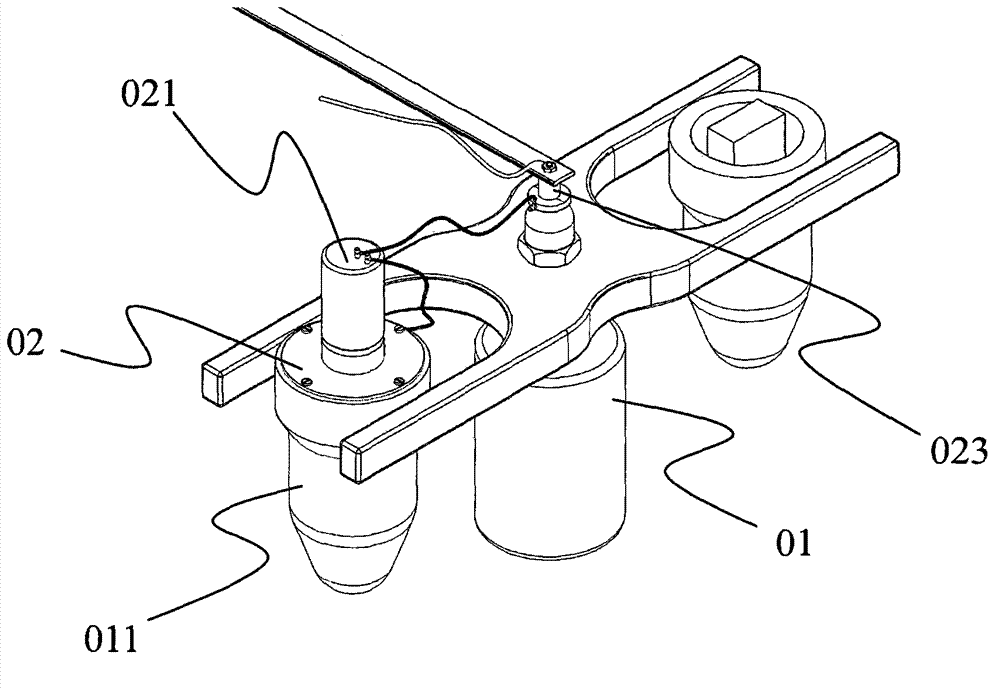
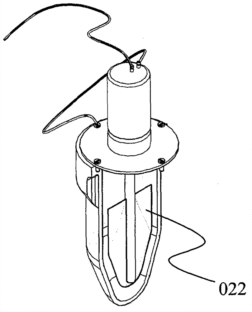
[0043] The specific technical solution is to install a rotating excitation device 02 in the centrifuge cup 011 of the existing swinging rotor centrifuge 01, which can rotate and stir the materials in the cup during the centrifugation process. The rotary excitation device can be fixed on the mouth of the centrifuge cup with a flat stirring blade 022 driven by a DC motor 021, and a slip ring carbon brush 023 is arranged on the central axis of the centrifuge, and one phase of the two-phase power line of the DC motor It is directly connected to the centrifuge, the other phase is connected to the voltage regulating DC power supply through the slip ring carbon brush, and the other phase of the DC power supply is connected to the centrifuge. There is a large gap between the edge of the flat stirring blade and the wall of the centrifugal cup.

[0044] When working, put the slurry material in the ce...

Embodiment 2

[0045] Example 2 , Straight blade centrifugal separation device.

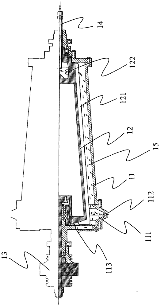
[0046] Concrete scheme, its centrifugal device comprises outer drum 11, inner drum 12, differential transmission device 13, feed pipe 14, and outer drum is the hollow round drum of conical frustum shape, and the side is provided with the weight of band chute 111 respectively near lower bottom surface and lower bottom surface. The material outlet 112 and the light material outlet 113, the inner drum as the mechanical excitation device is a round platform similar in shape to the outer drum, and several straight blades 121 are arranged on the side. The end with the smaller diameter of the outer drum and the inner drum is called the top end, and the end with the larger diameter is the bottom end. The differential transmission device has the same structure as the corresponding part of the existing decanter centrifuge, and its function is to drive the outer drum and the discharge screw to rotate at a differential s...

Embodiment 3

[0048] Example 3 , Double helical blade centrifugal separation device.

[0049] The device includes an outer drum 21 , an inner drum 22 , an excitation screw 221 , a heavy material discharge screw 222 and a differential transmission device 23 . The outer drum is a centrifugal device, which consists of a straight cylinder and a cone whose bottom surface matches the straight cylinder to form a cavity. The inner drum and the excitation screw are mechanical excitation devices. The inner drum and the outer drum are similar in shape, and the inner drum and the outer drum jointly form a separation chamber 24 . The straight part and the conical part of the inner drum and the outer drum are respectively called the straight section and the cone section, the junction of the straight section and the cone section of the inner drum and the outer drum is called the shoulder, and the other end of the straight section is called the bottom. A feed inlet 223 is arranged in the middle of the ...


PUM


Abstract

The invention relates to a centrifugal device used for separating fine particles different in density in slurry and discloses a centrifugal separation device. The separation principle of existing centrifugal devices for separating fine slurry by proportion is characterized in that the slurry is kept in relative movement with a reel under the effect of inertia generated when the slurry flows along with rotation of the centrifugal reel, therefore laminar flow with velocity gradient is generated, and the purpose of separating by proportion is achieved by the aid of bagnold effect generated in the laminar flow. The devices have the defect that separation effect is affected due to the fact that the velocity gradient of the relative movement of the slurry is not easy to control. Through the centrifugal separation device, a mechanical excitation device capable of controlling action strength of the centrifugal separation device is utilized to apply dynamic excitation to a slurry material in a centrifugal field, the slurry material can be enabled to generate laminar flow having appropriate velocity gradient relatively to the centrifugal device, bagnold effect is enhanced, and the purpose of accurate separation is achieved accordingly.

Description

technical field [0001] The invention relates to a centrifugal device for separating fine particles of different densities in a slurry. Background technique [0002] Among the centrifuges for separating fine particles of different densities in slurries that have been put into widespread commercial use, there is a centrifuge with a bowl-shaped drum, which was first disclosed in Canadian Patent CA1111809A1, and in a series of patents or patent applications thereafter , including US4608040, US4846781, US5338284, US5462513, US5586965, US5601523, US6149572, US6796934, US2004013260, US20050026766, US20060135338, continuously improved and perfected, known as the Knelson centrifuge. The main structure of this type of separation equipment includes a vertical bowl-shaped drum that can rotate at high speed and one or more annular chutes located on the outer peripheral wall of the drum. A feeding pipe leads to the bottom of the drum. The impeller that can accelerate the rotation of the ...

Claims


Application Information

Patent Timeline
Patent Type & Authority Applications(China)
IPC IPC(8): B04B1/00B04B15/00B04B7/08B04B11/02
CPCB04B1/20B04B2001/205B04B15/12B04B5/0421B04B5/10B04B9/10
Inventor 张传忠彭勃
Owner QINZHOU AURASOURCE TECH
Why Eureka
Try Eureka