Engine cylinder block cast casting method

A technology for engine cylinder blocks and castings, applied in the field of castings, can solve problems such as poor tensile strength and hardness uniformity, achieve the effects of reducing wall thickness sensitivity, reducing microstructure differences, and improving mechanical properties

Inactive Publication Date: 2014-02-19
WUJIANG HYDRAULIC COMPONENTS FOUNDRY
View PDF11 Cites 4 Cited by
  • Summary
  • Abstract
  • Description
  • Claims
  • Application Information

AI Technical Summary

Problems solved by technology

[0004] In order to solve the deficiencies in the background technology, the purpose of the present invention is to overcome the defects of the background technology and provide a casting method for engine bloc

Method used


Image

  • Engine cylinder block cast casting method
  • Engine cylinder block cast casting method
  • Engine cylinder block cast casting method

Examples


Example Embodiment

[0023] Example 1

[0024] The metal charge is melted into molten iron in the smelting furnace. When the temperature of the molten iron reaches 1520~1550℃, the molten iron is flushed into the ladle from the smelting furnace, and the molten iron starts to flush into the ladle until the amount of molten iron is 5% of the total weight of the molten iron. In the fourth period, the A inoculant with a weight of 0.3% of the total weight of the molten iron from the furnace and a particle size of 0.2-0.6mm will be uniformly and dispersedly dispersed into the liquid stream through a quantitative funnel, and the molten iron will undergo the first inoculation treatment in the ladle; When the molten iron temperature is 1400~1420℃, inject the molten iron from the ladle into the casting cavity, from the amount of molten iron injected to one-fourth of the total weight of the molten iron to four-fifths of the total weight of the molten iron. Within a period of time, the B inoculant with a weight o...

Example Embodiment

[0026] Example 2

[0027] The only difference from Example 1 is that the time for adding the inoculant is not limited in the first inoculation treatment and the second inoculation treatment.
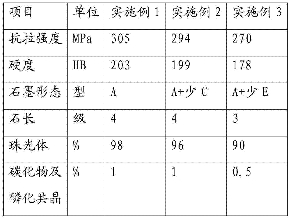
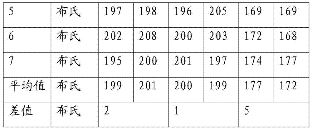
[0028] The results of testing castings produced according to the process of Example 2 are shown in Tables 1-1 and 2-2.

Example Embodiment

[0029] Example 3

[0030] The only difference from the embodiment is that the one-time inoculation process in the background technology is used, that is, the metal charge is melted into molten iron in the smelting furnace. When the temperature of the molten iron reaches 1520-1550°C, the molten iron is poured into the ladle from the smelting furnace. A inoculant with a weight of 0.3% of the total weight of the molten iron and a particle size of 0.2 to 0.6 mm or a B inoculant with a weight of 0.07% to 0.13% of the total weight of the molten iron and a particle size of 0.4 to 0.8 mm is placed in the ladle in advance At the bottom, when the molten iron is flushed into the ladle, an inoculation process is performed in the ladle, and after the inoculation process, the molten iron is flushed into the casting cavity for pouring. Among them, all the parameters of A inoculant or B inoculant are the same as those in Example 1.

[0031] The results of testing castings produced by the process ...


PUM

PropertyMeasurementUnit
Granularityaaaaaaaaaa

Abstract

The invention provides an engine cylinder block cast casting method. The engine cylinder block cast casting method is characterized in that metal-stream inoculation is carried out twice, and the time when a nucleating agent is added, the usage amount of the nucleating agent, the particle size and temperature of the nucleating agent, constituents of the nucleating agent and the mass percents of the constituents are controlled in each time of metal-stream inoculation. By means of the method, the problem that an existing cast is poor in tensile strength and uniformity of hardness can be solved, the metallographic phase, hardness, mechanical performance and other properties of the cast are greatly improved, and the mechanical property stability of the cast is greatly improved.

Description

technical field [0001] The invention relates to a casting casting method, in particular to a casting method of an engine cylinder casting. Background technique [0002] Cylinder block is the key component of the automobile engine and one of the most important working parts in the engine work. With the continuous increase of the horsepower of the truck, the engine power needs to be continuously improved, and the country's emission requirements are becoming more and more stringent. The various loads borne by the engine are increasing sharply, making the engine develop in the direction of high speed, strengthening, and long life. Therefore, more stringent requirements are put forward for the design and material performance of the engine cylinder block, especially the material performance will directly affect the engine. various performances. [0003] The internal structure of the cylinder block is complex, and most of them are cast by liquid casting hydraulic technology. Bott...

Claims


Application Information

Patent Timeline
IPC IPC(8): B22D1/00
Inventor 浦巧生
Owner WUJIANG HYDRAULIC COMPONENTS FOUNDRY
Why Eureka
Try Eureka