Cylinder head camshaft oil hole chamfering device

A technology of chamfering device and camshaft, which is applied in the direction of positioning device, drilling/drilling equipment, clamping, etc., can solve the problems of poor chamfering quality and low chamfering efficiency, and achieve good chamfering quality and chamfering The effect of high efficiency and simple support structure

Inactive Publication Date: 2014-02-19
ZHEJIANG GEELY POWERTRAIN CO LTD
View PDF6 Cites 6 Cited by
  • Summary
  • Abstract
  • Description
  • Claims
  • Application Information

AI Technical Summary

Problems solved by technology

[0003] The purpose of the present invention is to overcome the problem that the two camshaft oil holes are difficult to be clamped at one time on the existing equipment to realize the chamfering operation, and the chamfering can only be done manually, and the chamfering quality is poor and the chamfering efficiency is low. Insufficient, to provide a cylinder head camshaft oil hole chamfering device that realizes chamfering operation in one clamping, has better chamfering quality and higher chamfering efficiency

Method used


Image

  • Cylinder head camshaft oil hole chamfering device
  • Cylinder head camshaft oil hole chamfering device

Examples


Embodiment Construction

[0015] The present invention will be further described below in conjunction with the accompanying drawings.

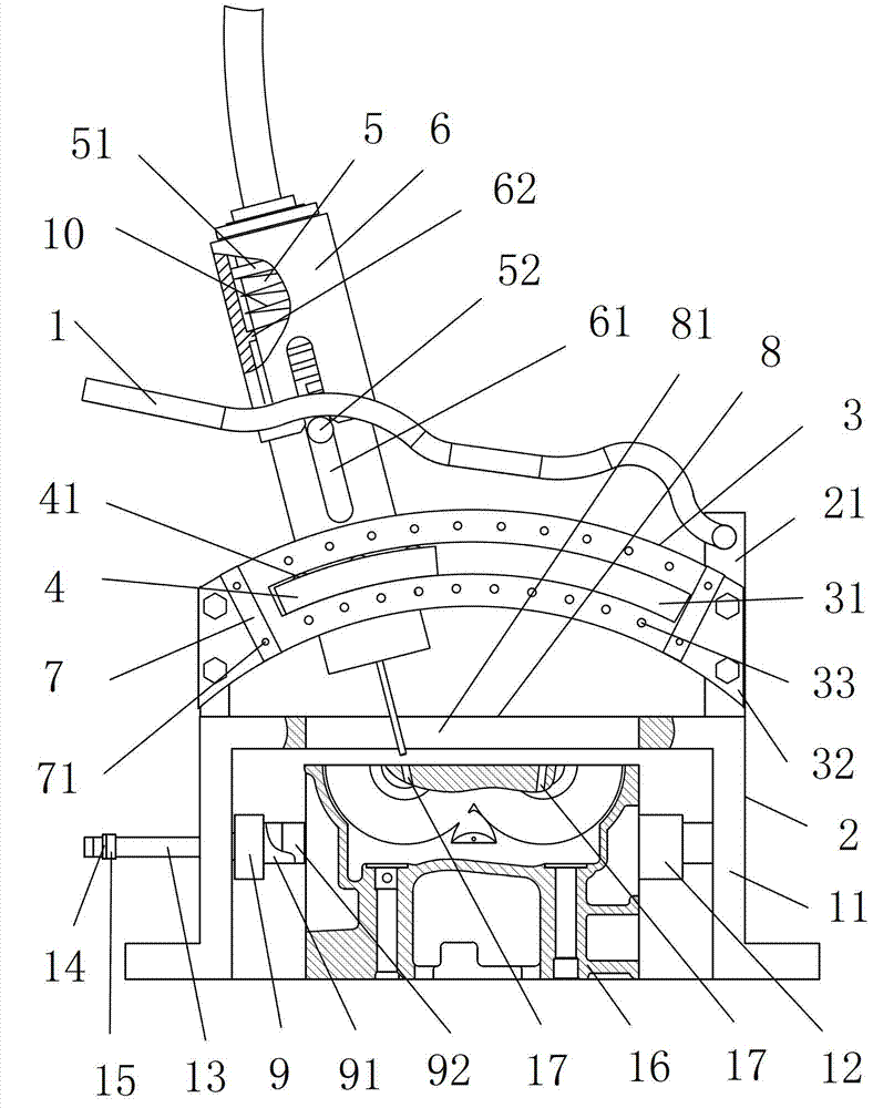
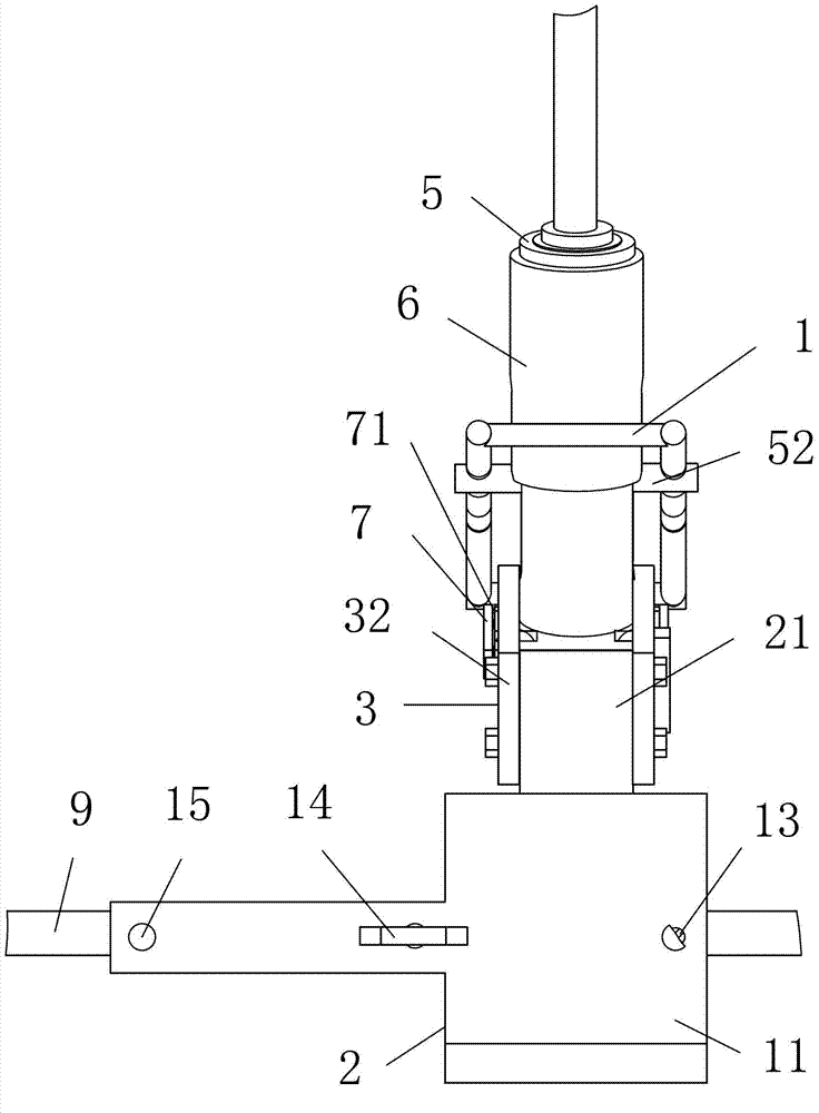
[0016] as attached figure 1 , attached figure 2 Shown: a cylinder head camshaft oil hole chamfering device, including a support 2 with two upper side plates 21, a beam 3 with a circular arc-shaped chute 31 and two ends connected to an upper side plate 21, There is a chamfering mechanism and a corner limiting mechanism of the slide block 4 matched with the arc-shaped chute 31 .

[0017] In this embodiment, the crossbeam 3 includes two support plates 32 whose two ends are screwed to the side ends of an upper side plate 21; each arc-shaped chute 31 is located on a support plate 32 and runs through the support plate The two sides of 32; Arc-shaped chute 32 takes the intersection of the axes of the camshaft oil holes 17 of two cylinder heads 16 as the axis.

[0018] The chamfering mechanism includes an air drill 5 with an upper convex ring 51 and a drill pin 52 on the s...


PUM


Abstract

The invention relates to the field of manufacturing of automotive engine cylinder heads, in particular to a cylinder head camshaft oil hole chamfering device. The cylinder head camshaft oil hole chamfering device comprises a support, a crossbeam, a chamfering mechanism and a corner limit mechanism, wherein the support is provided with two upper side plates, the crossbeam with each end connected with one upper side plate is provided with a circular arc sliding groove, and the chamfering mechanism is provided with a slider matched with the circular arc sliding groove. When the cylinder head camshaft oil hole chamfering device is used, a cylinder head is placed in the support, the chamfering mechanism is pulled, the corner limit mechanism is used to limit, and the chamfering mechanism chamfers one camshaft oil hole of the cylinder head; the chamfering mechanism is pulled, the corner limit mechanism is used to limit, and the chamfering mechanism chamfers the other camshaft oil hole of the cylinder head. The cylinder head camshaft oil hole chamfering device achieves chamfering operation by one-time clamping, and is good in chamfering quality and high in chamfering efficiency.

Description

technical field [0001] The invention relates to the field of manufacturing automobile engine cylinder heads, in particular to a cylinder head camshaft oil hole chamfering device. Background technique [0002] The utility model of Chinese patent announcement number CN 201934165U discloses a kind of engine cylinder head camshaft pressure lubricating oil hole, comprises cylinder head cover surface, and cylinder head cover surface is formed with spark plug hole, tappet hole and water plug hole, cylinder head cover The two ends of the surface are shaped on camshaft holes, and tile covers are arranged above the shaft holes, and a camshaft is installed between the camshaft holes and the tile covers, and pressure lubricating oil holes are formed in the described camshaft holes. The traditional cylinder head is equipped with two camshaft oil holes arranged laterally and the angle between the two axes is 15 degrees to 21 degrees as shown in the attached figure; there are often burrs i...

Claims


Application Information

Patent Timeline
Patent Type & Authority Applications(China)
IPC IPC(8): B23Q3/00B23D79/00B23B45/04
CPCB23D79/00B23Q1/26B23Q3/062
Inventor 黄财明许优燕宋文平毕家明孙艳陈杰王瑞平
Owner ZHEJIANG GEELY POWERTRAIN CO LTD
Why Eureka
Try Eureka