
Elevated steel lattice plate

A steel grating and high-profile technology, applied in the field of steel grating, can solve problems such as low height and failure to meet installation requirements, and achieve the effect of improving adaptability

Inactive Publication Date: 2014-02-19
TIANCHANG FEILONG BRAND STEEL GRID
View PDF0 Cites 0 Cited by
  • Summary
  • Abstract
  • Description
  • Claims
  • Application Information

AI Technical Summary

Problems solved by technology

In the steel grating design process, in order to save materials, the height of the steel grating is controlled within the predetermined range under the premise of meeting the load-bearing requirements; however, in the actual application process, according to the structural characteristics of the supporting components, ordinary steel grating The height of the grille is often low, which cannot meet the installation requirements

Method used


Image

  • Elevated steel lattice plate
  • Elevated steel lattice plate

Examples


Embodiment Construction

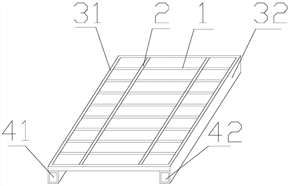
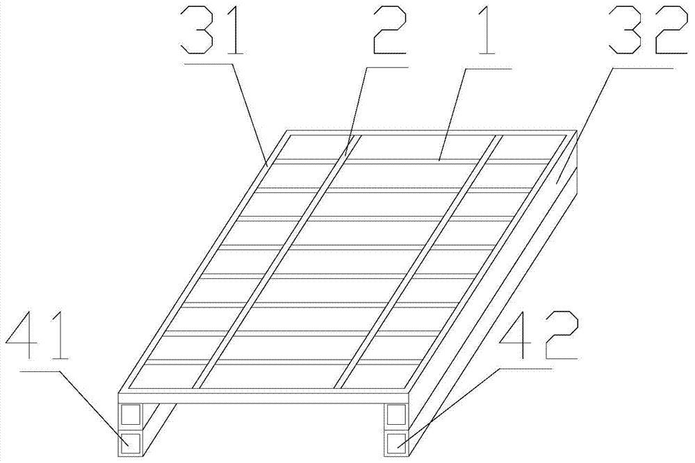
[0012] like figure 1 and figure 2 as shown, figure 1 It is a structural schematic diagram of an elevated steel grating proposed by the present invention, figure 2 It is a schematic structural diagram of an elevated steel grating proposed in the second embodiment of the present invention.

[0013] refer to figure 1 and figure 2 , an elevated steel grating proposed by the present invention, including a plurality of flat steels 1, a plurality of twisted square steels 2, two surrounding steels 31, 32 and two equal-height overhead fittings 41, 42, two The overhead fittings 41, 42 are both made of a square steel pipe or the two overhead fittings 41, 42 are welded up and down by two square steel pipes; a plurality of twisted square steel bars 2 are placed horizontally on a plurality of evenly arranged The flat steel 1 is fixedly connected by pressure welding, the two surrounding steel 31, 32 are transversely welded on the two end faces of the multiple flat steel 1, and the tw...


PUM


Abstract

The invention discloses an elevated steel lattice plate comprising a plurality of flat bars (1), a plurality of torsional square bars (2) , two side bars (31 and 32), and two elevated tubes (41 and 42) equal in height. The elevated tubes (41 and 42) are both square steel tubes, or each of the elevated tubes (41 and 42) is formed by stack-welding an upper square steel tube and a lower square steel tube. The torsional square bars (2) are transversely arranged and fixedly connected onto the flat bars (1) evenly arranged at preset intervals by means of press-welding. The side bars (31 and 32) are transversely welded on end faces of the flat bars (1). The elevated tubes (42 and 42) are transversely welded at the bottoms of the ends of the flat bars (1) respectively. The elevated tubes are disposed at the bottom of the steel lattice plate, both the elevated tubes are square steel tubes, or each elevated tube is formed by stack-welding the upper and lower square steel tubes, mounting operations of steel lattice plates having different mounting height requirements are achieved, and the steel lattice plate is more applicable.

Description

technical field [0001] The invention relates to the technical field of steel gratings, in particular to an elevated steel grating. Background technique [0002] In the prior art, the steel grating includes pressure-bearing flat steel and cross bars, and multiple load-bearing flat steel bars are arranged and welded according to predetermined spacing and cross bars. The structural stability and strength of the steel grating are extremely high. The application in the industrial field is very extensive. Since the steel grating has a square grid structure, its dimensions can be made according to actual application requirements, and it can be square, arc, circular and composite structures. Therefore, the steel grating can meet the application requirements of different application scenarios . In the steel grating design process, in order to save materials, the height of the steel grating is controlled within the predetermined range under the premise of meeting the load-bearing re...

Claims


Application Information

Patent Timeline
Patent Type & Authority Applications(China)
IPC IPC(8): F16S3/08
Inventor 孙长志
Owner TIANCHANG FEILONG BRAND STEEL GRID
Learn More