Burner of direct-injection type cooker combustor

A burner, direct injection technology, applied in the direction of burner, gas fuel burner, combustion method, etc., can solve the problems of waste gas, low power, insufficient gas combustion, etc.

Inactive Publication Date: 2014-02-19
ZHONGSHAN QIAO TAITAI KITCHEN & ELECTRICAL APPLIANCES CO LTD
View PDF6 Cites 6 Cited by
  • Summary
  • Abstract
  • Description
  • Claims
  • Application Information

AI Technical Summary

Problems solved by technology

Existing problems are: insufficient combustion of gas, wastin

Method used


Image

  • Burner of direct-injection type cooker combustor
  • Burner of direct-injection type cooker combustor
  • Burner of direct-injection type cooker combustor

Examples


Embodiment 1

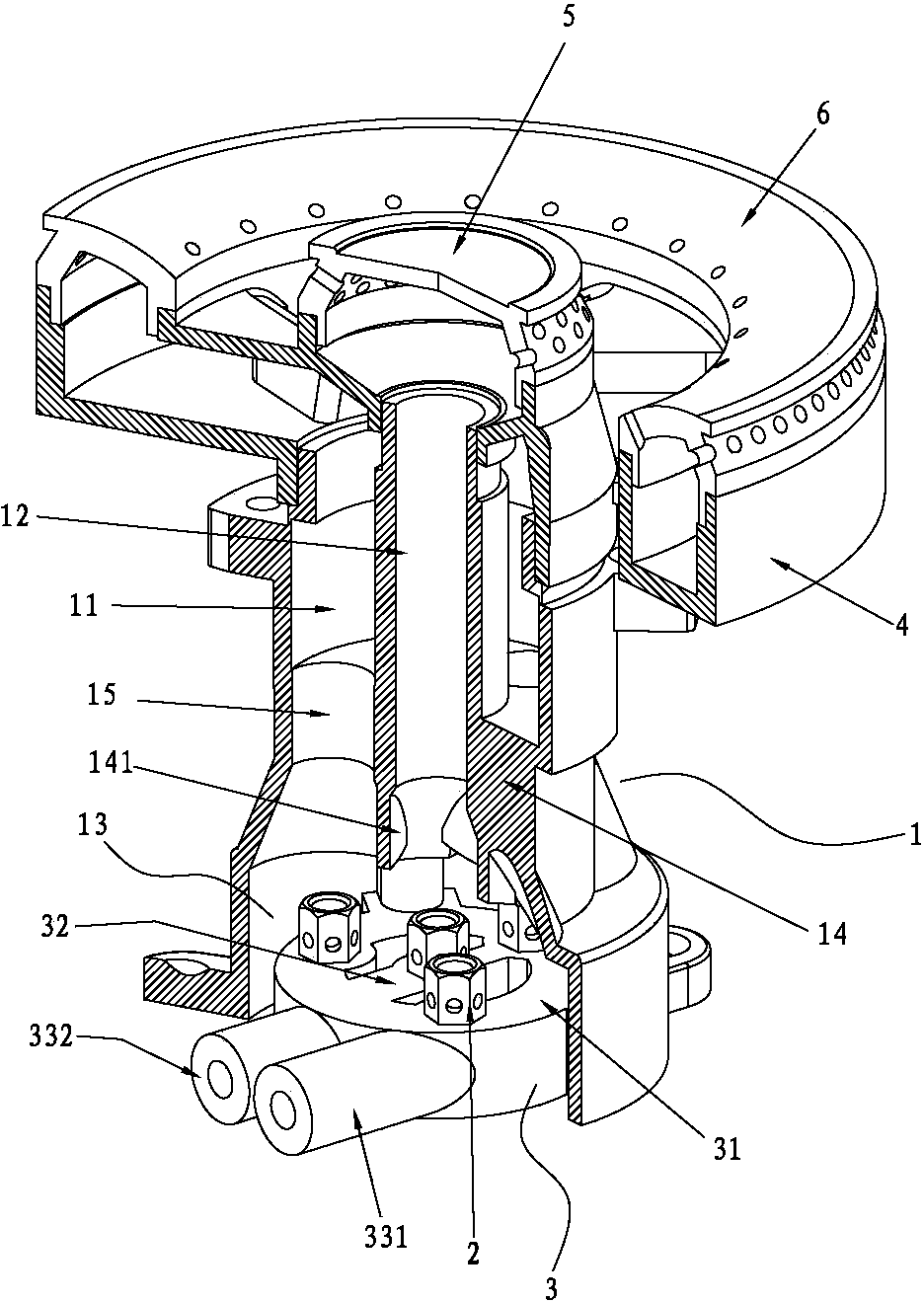
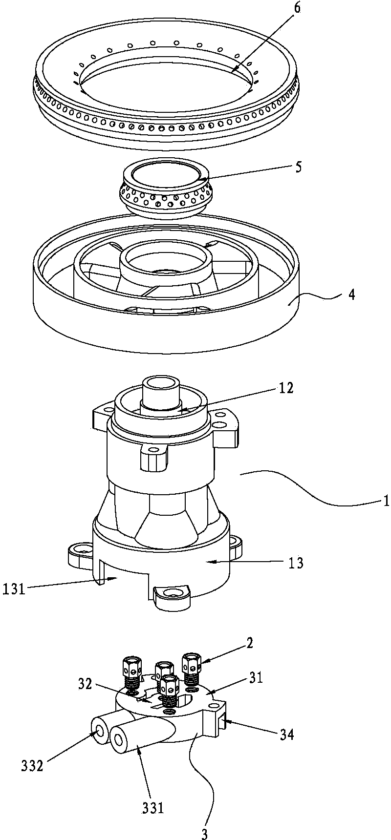
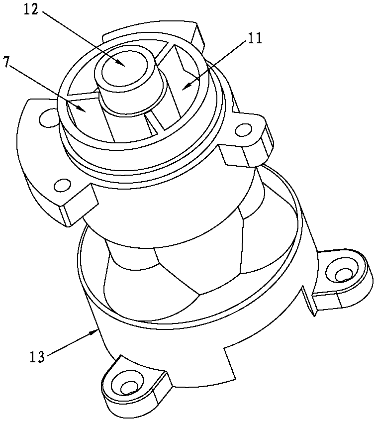
[0027] Such as figure 1 , figure 2 As shown, a burner head of a direct-injection stove burner includes a burner body 1 and a nozzle 2. The burner body 1 has an outer ring gas mixture chamber 11, a central air intake pipe 12 and a premix chamber 13. The ring mixing chamber 11 and the premixing chamber 13 communicate through the air guide hole 15 on the partition 14; the lower end of the central air intake pipe 12 is fixedly connected with the central air intake hole 141 on the partition 14, and the air guide hole 15 surrounds the central air intake Hole 141, the lower end of the central air intake pipe 12 communicates with the premix chamber 13 through the central air intake hole 141; the nozzle 2 is opposite to the central air intake hole 141 and the air guide hole 15; the burner body 1 is integrally formed.

[0028] The upper end area of ​​the air guide hole 15 is small and the lower end area is large, that is to say: the air guide hole 15 is in the shape of a truncated con...

Embodiment 2

[0041] Such as Figure 4 shown, refer to figure 1 As shown, a burner head of a direct-injection cooker burner includes a burner body 1 and a nozzle 2. The burner body has a mixed gas cavity 11, a central air intake pipe 12 and a premixed cavity 13. The mixed gas cavity 11 It communicates with the premixing chamber 13 through the air guide hole 15 on the partition 14; the lower end of the central air intake pipe 12 is fixedly connected with the central air intake hole 141 on the partition plate, and the air guide hole 15 surrounds the central air intake hole 141, and the central air intake pipe The lower end of 12 communicates with the premix chamber 13; the nozzle 2 is opposite to the central air inlet 141 and the air guide hole 15; the number of the mixed air chamber 11 matches the number of the air guide hole 15;

[0042] The lower end of the air guide hole 15 has a compression chamber, which is in the shape of a truncated cone.


PUM


Abstract

The invention provides a burner of a direct-injection type cooker combustor. The burner of the direct-injection type cooker combustor comprises a burner body and nozzles. An outer annular mixed gas cavity, a center gas inlet tube and a pre-mixed cavity are formed in the burner body. The outer annular mixed gas cavity is communicated with the pre-mixed cavity through a gas guiding hole formed in a partition plate. The lower end of the center gas inlet tube is fixedly connected with a center gas inlet hole in the partition plate. The gas guiding hole surrounds the center gas inlet hole. The lower end of the center gas inlet tube is communicated with the pre-mixed cavity. The nozzles are opposite to the center gas inlet hole and the gas guiding hole. The gas guiding hole is of a circular truncated cone shape. The nozzles are arranged on gas outlet holes formed in a nozzle base. The portion, located on the center of an annular gas inlet cavity, of a direct gas inlet tube is provided with gas outlet holes. The nozzle base is arranged in the pre-mixed cavity or the nozzle base is arranged below the pre-mixed cavity. Gas and air are mixed in advance in the pre-mixed cavity. Sufficient air is guaranteed. The gas and the air enter the outer annular mixed gas cavity to be further mixed after being compressed and released by the gas guiding hole, and therefore the purposes that the gas and the air are completely mixed, the gas is burned completely, and energy is saved are achieved.

Description

technical field [0001] The invention relates to a household burner, in particular to a stove head of a household burner. Background technique [0002] In the current prior art, a burner head of a direct-injection cooker burner includes a burner body and a nozzle. The upper part of the burner body has a gas mixture chamber, and the lower part is a premix chamber. The gas mixture chamber and the premix chamber are connected through an air guide hole, and the nozzle is arranged on the nozzle seat of the premix chamber. Existing problems are: gas combustion is insufficient, waste gas, only one fire cover is applicable, and the power is small. Contents of the invention [0003] The object of the present invention is to provide a burner head of a direct-injection stove burner, which not only has high power, but also fully burns gas and saves energy. [0004] The present invention is realized in the following way: a burner head of a direct-injection cooker burner includes a bur...

Claims


Application Information

Patent Timeline
IPC IPC(8): F23D14/02F23D14/62
Inventor 曾祥林
Owner ZHONGSHAN QIAO TAITAI KITCHEN & ELECTRICAL APPLIANCES CO LTD
Why Eureka
Try Eureka