Time interval measurement calibration device based on light path delay and measurement calibration method thereof

A technology of time interval measurement and optical path delay, applied in the direction of time interval measurement devices, instruments, etc., can solve problems such as inconvenience in use, and achieve the effects of extended range, compact structure and high stability

Inactive Publication Date: 2014-02-19
HARBIN ENG UNIV
View PDF12 Cites 6 Cited by
  • Summary
  • Abstract
  • Description
  • Claims
  • Application Information

AI Technical Summary

Problems solved by technology

This method has the advantages of high calibration resolution and high precision, but the variable delay line of this method needs to be calibrated before use, and ...

Method used


Image

  • Time interval measurement calibration device based on light path delay and measurement calibration method thereof

Examples


Embodiment Construction

[0022] The purpose of the present invention is to provide a high-precision time interval measurement and calibration method based on optical path delay for a high-precision time interval measurement system. The time interval measurement system is calibrated by measuring the distance traveled by the optical signal to obtain its flight time. In order to achieve the purpose of calibrating a high-precision time interval measurement system, a high-precision time interval calibrating device is provided so that the method can be implemented.

[0023] Above-mentioned purpose realizes through following technical scheme:

[0024] The method for measuring and calibrating time intervals based on optical path delay according to the present invention includes:

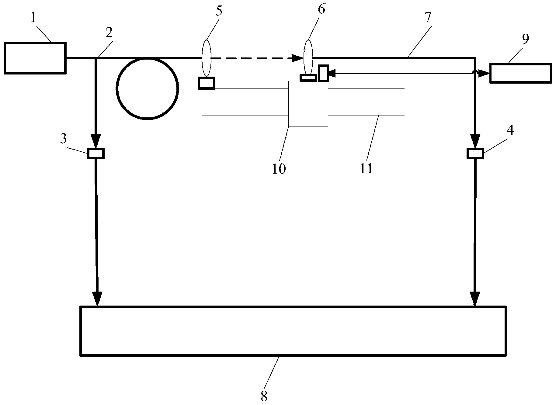
[0025] ①. First, adjust the whole system before detection, turn on the light source, and the optical pulse signal emitted at a certain frequency passes through the Y-shaped optical fiber and is divided into two beams, one of which i...


PUM


Abstract

The invention belongs to the field of time measurement, and particularly relates to a time interval measurement calibration device based on light path delay and a measurement calibration method of the device. The time interval measurement calibration device based on light path delay comprises a light source (1), a Y-type optical fiber (2), a first photoelectric detector (3), a second photoelectric detector (4), an emitting lens (5), a receiving lens (6), a light transmitting optical fiber (7), a time interval measurement system (8), a displacement measurement system (9), a moving platform (10) and a guide rail (11). The time interval measurement calibration device based on light path delay is simple in principle, compact in structure and convenient to trace for the source; time resolution of calibration is high, and uncertainty of the system is small; the device is convenient and flexible to operate, good in repeatability and high in stability.

Description

technical field [0001] The invention belongs to the field of time measurement, in particular to a time interval measurement and calibration device based on optical path delay and a measurement and calibration method thereof. Background technique [0002] Time interval measurement is widely used in aerospace, radar positioning, laser ranging, detonation physics, shock wave physics, and nuclear physics detection. With the increasing requirements for time interval accuracy, how to optimize the time interval measurement system? Calibration becomes a difficult problem. [0003] At present, the time interval calibration at home and abroad mainly uses existing equipment and instruments for calibration. When the accuracy of the time interval measurement system reaches a certain level, there is no better measurement system for calibration. The Great Wall Radio Metrology and Testing Institute adopts high-speed pulse Generator, width power divider, coaxial air delay line, etc. constit...

Claims


Application Information

Patent Timeline
IPC IPC(8): G04F13/02
Inventor 钟志单明广
Owner HARBIN ENG UNIV
Why Eureka
Try Eureka