Distributed photovoltaic power station/transformer substation 10kV bus grid-integration structure

A distributed photovoltaic and photovoltaic power station technology, applied in photovoltaic power generation, electrical components, climate change adaptation and other directions, can solve problems such as low reliability, low efficiency of fault reporting, and difficulty in effectively removing faults, reducing the scope of power outages. Effect

Inactive Publication Date: 2014-02-26
SHANGHAI MUNICIPAL ELECTRIC POWER CO
View PDF4 Cites 0 Cited by
  • Summary
  • Abstract
  • Description
  • Claims
  • Application Information

AI Technical Summary

Problems solved by technology

Therefore, it is imminent to study the grid-connection of electricity generated by photovoltaic power plants into the existing grid. , it is difficult to effectively remove the fault after a fault occurs

Method used


Image

  • Distributed photovoltaic power station/transformer substation 10kV bus grid-integration structure
  • Distributed photovoltaic power station/transformer substation 10kV bus grid-integration structure

Examples


Embodiment Construction

[0017] The present invention will be further elaborated below by describing a preferred specific embodiment in detail in conjunction with the accompanying drawings.

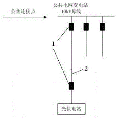
[0018] like figure 1 As shown, a grid-connected connection structure of a distributed photovoltaic power station and a 10kV busbar of a substation, the photovoltaic power station and the 10kV busbar of the substation are connected through a cable 2, including: a cable set on the cable line connecting the 10kV busbar of the substation and the photovoltaic power station Two sets of protection devices 1 are provided on the side of the busbar and the side of the photovoltaic power station respectively.

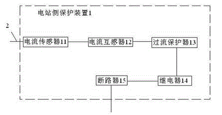
[0019] like figure 2 As shown, each protective device 1 includes: a current sensor 11, a current transformer 12, an overcurrent protector 13, a relay 14, and a circuit breaker 15, wherein the current sensor 11 is arranged on the cable 3; the current transformer 12 communicates with the The output end of current se...


PUM


Abstract

The invention discloses a distributed photovoltaic power station / transformer substation 10kV bus grid-integration structure. The photovoltaic power station is connected with a transformer substation 10kV bus through a cable. The structure comprises two protectors connected on the cable line between the transformer substation 10kV bus and the photovoltaic power station, wherein the two protectors are respectively arranged at the bus side and the photovoltaic power station side. The structure can ensure the power supply reliability after grid integration, reduce the power cut range and effectively implement failure removal.

Description

technical field [0001] The invention relates to a grid-connected structure for power generation integrated into a power grid, in particular to a grid-connected access structure for a distributed photovoltaic power station and a 10kV busbar of a substation. The capacity of a single grid-connected point of the distributed photovoltaic power generation is 1 MW to 6 MW. Background technique [0002] Since the 20th century, especially since the 1970s, with the rapid development of the world economy, human demand for energy has doubled, and the energy industry has also developed on an unprecedented scale. However, some problems caused by this have also aroused the great attention of many countries. Countries that use coal and oil as their main primary energy sources not only face the problem of depletion of conventional energy sources, but also directly emit greenhouse gases and aerosols into the atmosphere due to the extensive use of fossil energy, which has caused global warming...

Claims


Application Information

Patent Timeline
IPC IPC(8): H02J3/38H02H7/26
CPCY02E10/563Y02A30/60Y02E10/56
Inventor 夏威张麟陈国新胡年平宓佳璟钱昊宏李春杰吴俊杰帅志飞周元棋
Owner SHANGHAI MUNICIPAL ELECTRIC POWER CO
Why Eureka
Try Eureka