
CMOS Schmidt trigger circuit

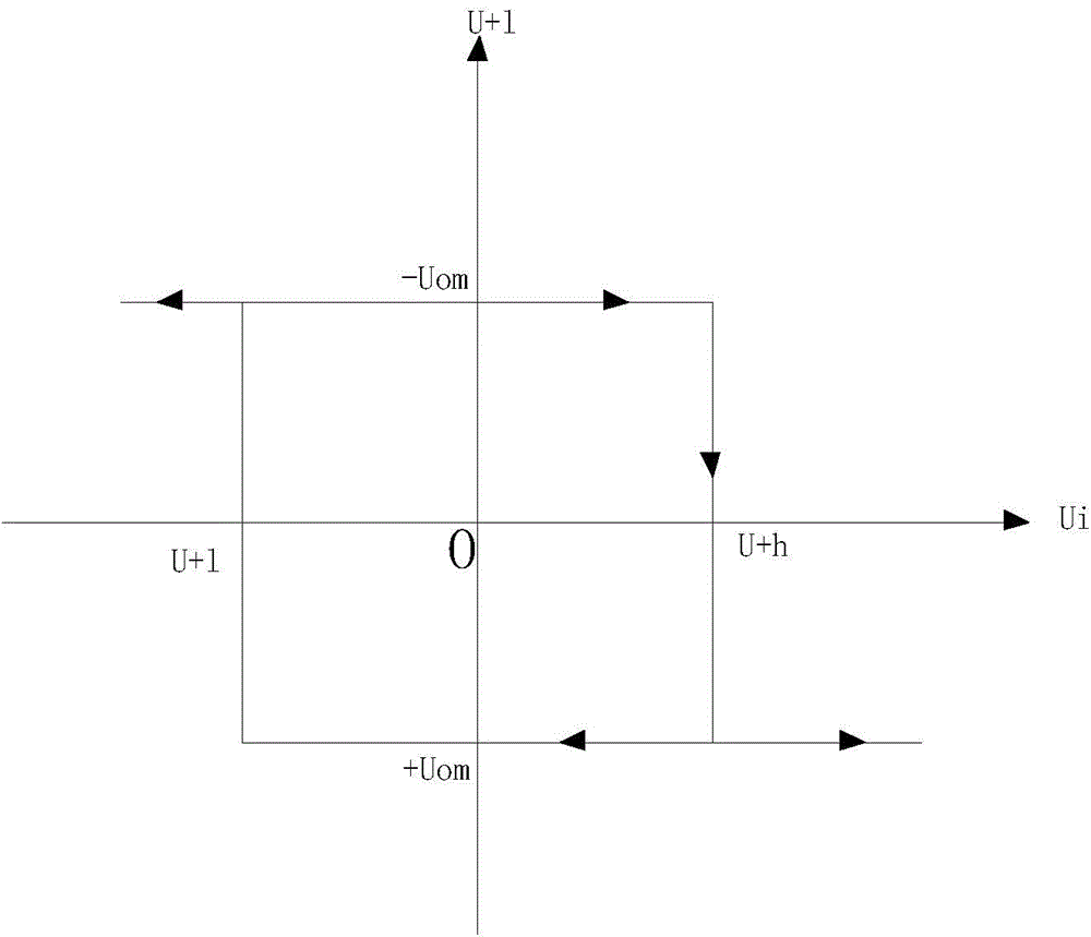
A Schmitt trigger, circuit technology, applied in electrical components, electrical pulse generation, pulse generation, etc., can solve the problems of adjusting the size of the output hysteresis window, large limitations, and use limitations.

Inactive Publication Date: 2014-02-26
SHANGHAI HUALI MICROELECTRONICS CORP
View PDF4 Cites 7 Cited by
  • Summary
  • Abstract
  • Description
  • Claims
  • Application Information

AI Technical Summary

Problems solved by technology

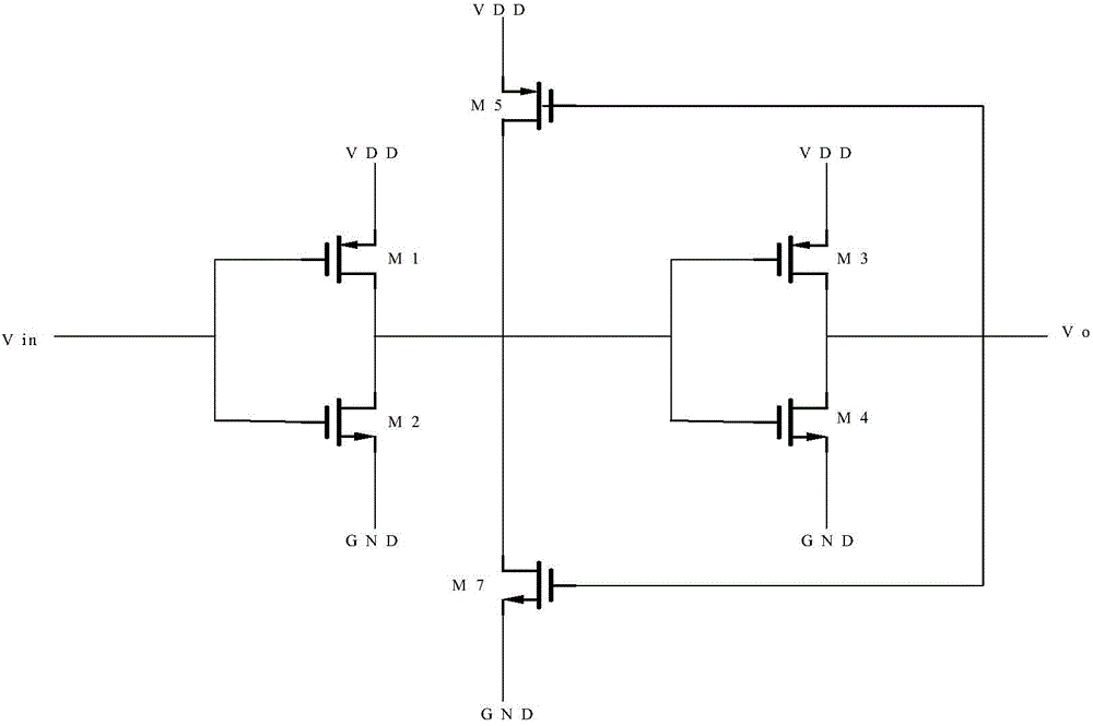
[0009] However, the hysteresis (hysteresis) of the Schmitt trigger circuit provided by this patent is deterministic, and the size of the output hysteresis window cannot be adjusted according to the actual usage, which has relatively large limitations and has certain usage restrictions during use.

Method used


Image

  • CMOS Schmidt trigger circuit
  • CMOS Schmidt trigger circuit
  • CMOS Schmidt trigger circuit

Examples


Embodiment Construction

[0035] The specific embodiment of the present invention will be further described below in conjunction with accompanying drawing:

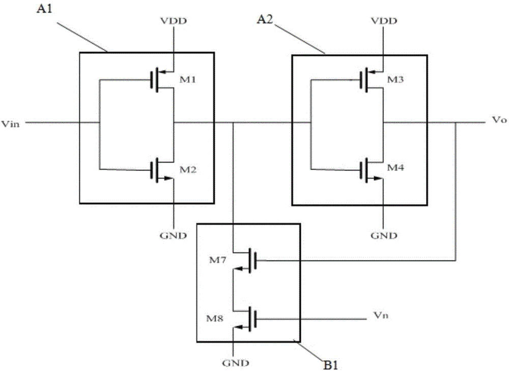
[0036] The present invention provides an adjustable CMOS Schmitt trigger circuit structure, such as image 3 As shown, the structure includes a first reverse circuit A1, a second reverse circuit A2 and a feedback circuit B1; the first reverse circuit A1 includes a first transistor M1 and a second transistor M2, and the second reverse circuit A2 includes a third The transistor M3 and the fourth transistor M4, the feedback circuit B1 includes the seventh transistor M7 and the eighth transistor M8.

[0037] The respective gates of the first transistor M1 and the second transistor M2 included in the first reverse circuit A1 are connected to the input signal Vin, the source of the first transistor M1 is connected to the power supply voltage VDD, and the source of the second transistor M2 is connected to the ground terminal GND, Wherein, the input sign...


PUM


Abstract

The invention provides a CMOS Schmidt trigger circuit which comprises a first reverse circuit, a second reverse circuit and a feedback circuit. The first reverse circuit and the second reverse circuit are connected with the feedback circuit. The first reverse circuit is connected with an input signal. The feedback circuit includes a seventh transistor and an eighth transistor. A node at which the gate of the seventh transistor and the second reverse circuit are connected is connected with an output signal. The gate of the eighth transistor is connected with an adjusting signal. By introducing the feedback circuit into the Schmidt trigger circuit and supplying the adjusting signal to feedback current, hysteresis can be adjusted through the adjusting signal and the feedback current.

Description

technical field [0001] The invention relates to the field of CMOS integrated circuits, in particular to a CMOS Schmidt trigger circuit. Background technique [0002] For a standard Schmitt trigger, when the input signal is higher than the positive threshold voltage, the output is high; when the input signal is lower than the negative threshold voltage, the output is low; when the input is between the positive and negative threshold voltages , the output signal does not change, that is to say, the threshold voltage corresponding to the output switching from high level to low level, or from low level to high level is different. The output changes only when the input signal changes sufficiently, hence the name flip-flop. This double-threshold action is called hysteresis (hysteresis characteristic), indicating that the Schmitt trigger has memory. Therefore, the traditional theory holds that the Schmitt trigger is a bistable multivibrator. [0003] In the prior art, a traditio...

Claims


Application Information

Patent Timeline
IPC IPC(8): H03K3/3565
Inventor 王文静王雅莉张瑞波
Owner SHANGHAI HUALI MICROELECTRONICS CORP
Learn More