
A concrete mixer with automatic water spraying

A technology for concrete mixers and mixing mechanisms, which is applied in cement mixing devices, clay preparation devices, liquid ingredient supply devices, etc. It can solve the problems of difficult mechanical layout, affecting the effect of mixing, and high labor intensity, so as to achieve convenient, accurate and convenient water supply. Clean scraping and high stirring efficiency

Active Publication Date: 2015-11-18
长兴云峰炉料有限公司
View PDF5 Cites 1 Cited by
  • Summary
  • Abstract
  • Description
  • Claims
  • Application Information

AI Technical Summary

Problems solved by technology

[0003] 1) There is no spray water adding device on the machine, and the mixing drum is in an open state. When this kind of mixer is mixing materials, it will generate very large dust, which will affect the work and cause waste of materials. The existing mixer water adding methods are: There are two types, one is to add water to the mixing drum with a water pipe when the mixer is rotating, and the other is to add water to the mixing drum with a bucket, which is not only labor-intensive, but also has poor work efficiency and unsafe factors;
[0004] 2) With the increase of working time, the inner wall of the mixing drum is easy to wear, which will lead to leakage of the mixing drum in severe cases. At the same time, because there is no cleaning device in the mixing drum, the concrete is easy to adhere to the inner wall, which affects the mixing effect , cleaning and maintenance are very inconvenient;
[0005] 3) The mixer with this feeding method is limited by the difficulty of operating space and mechanical layout, which restricts work efficiency and cost

Method used


Image

  • A concrete mixer with automatic water spraying
  • A concrete mixer with automatic water spraying
  • A concrete mixer with automatic water spraying

Examples


Embodiment Construction

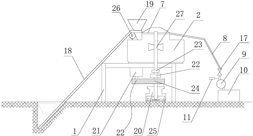
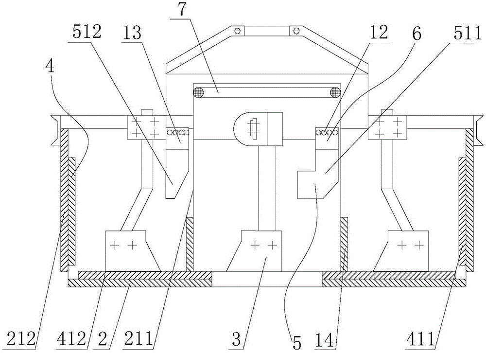
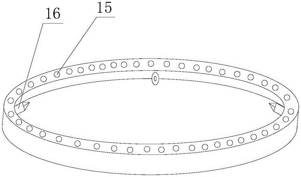
[0020] refer to figure 1 , figure 2 , image 3 , the present invention comprises a frame 1, a stirring mechanism, a feeding mechanism and a driving mechanism, the stirring mechanism is fixed above the frame 1, the driving mechanism is fixed below the frame 1, and the feeding mechanism is fixed on the bottom of the frame 1 On one side, the mixing mechanism includes a mixing drum 2 and a mixing blade 3, the mixing blade 3 is installed in the mixing drum 2, and the inner wall of the mixing drum 2 is provided with a liner 4 and a scraper 5, and the liner 3 and the The mixing drum 1 is screwed and fixed, and there is a gap between the scraper 5 and the inner wall of the mixing drum 2. The scraper 5 is fixed on the mixing drum 2 through the gap adjustment device 6, and the mixing drum 2 is also provided with a water spray pipe 7. The water inlet of the water spray pipe 7 is connected with a water inlet pipe 8, and the water inlet pipe 8 is connected with a water storage tank 10 t...


PUM


Abstract

The invention discloses a concrete mixer with an automatic water spraying function. The concrete mixer comprises a rack, a mixing mechanism, a loading mechanism and a driving mechanism, wherein the loading mechanism is fixed on one side of the rack; the mixing mechanism comprises a mixing drum and mixing blades; the mixing blades are arranged in the mixing drum; a liner plate is fixedly screwed with the mixing drum; a scraper is fixed on the mixing drum through a gap regulation device; a water spraying pipe is also arranged in the mixing drum; a water inlet pipe is connected to a water inlet of the water spraying pipe; a water storage tank is connected to the water inlet pipe through an electric pump. According to the concrete mixer, the water spraying pipe is arranged in the mixing drum, and water is supplied to the water spraying pipe through the electric pump to realize the automatic water addition of the mixing drum; the scraper and the screwed liner plate are arranged on the inner wall of the mixing drum, so that the thickness of the inner wall of the mixing drum is increased, and damage to the mixing drum is prevented; due to the arrangement of the scraper, concrete adhered to the mixing drum can be scraped; the position of the scraper can be changed by regulating the gap regulation device, so that the concrete can be conveniently cleaned and scraped; compared with the prior art, the concrete mixer has the advantages of quick and accurate water supply, convenience in operation, high mixing efficiency and low equipment damage rate.

Description

【Technical field】 [0001] The invention relates to the field of building concrete mixing equipment, in particular to a concrete mixer for automatic water spraying. 【Background technique】 [0002] The basic structure of the existing concrete mixer is to install a mixing device on a frame. The mixing device generally only consists of a mixing drum and a mixing blade. The operation method of the driving motor for the rotation of the mixing blade is to mix the materials on the ground first, and then extract and move them to the feeding port by other equipment through hydraulic or mechanical means. The following problems exist in this small and medium-sized concrete mixer: [0003] 1) There is no spray water adding device on the machine, and the mixing drum is in an open state. When this kind of mixer is mixing materials, it will generate very large dust, which will affect the work and cause waste of materials. The existing mixer water adding methods are: There are two types, one...

Claims


Application Information

Patent Timeline
Patent Type & Authority Patents(China)
IPC IPC(8): B28C7/12B28C5/16
CPCB28C5/0806B28C5/16B28C7/126
Inventor 佘云锋佘成其吴建华
Owner 长兴云峰炉料有限公司
Learn More