Supercharge Your Innovation With Domain-Expert AI Agents!

A rear automobile lamp detecting clamp of an automobile lamp air tightness detecting machine

A technology for detecting fixtures and rear lights, applied in the direction of detecting the appearance of fluid at the leakage point, using liquid/vacuum degree for liquid tightness measurement, etc., can solve the problem that it is impossible to detect all unqualified products, and there is no such airtightness Problems such as airtightness detection and waste of labor costs, etc., to achieve effective and rapid airtightness detection, reduce labor costs, and reduce production costs

Inactive Publication Date: 2014-03-05
苏州恩意精密机械有限公司
View PDF5 Cites 0 Cited by
  • Summary
  • Abstract
  • Description
  • Claims
  • Application Information

AI Technical Summary

Problems solved by technology

[0002] In modern industrial manufacturing, many complex machines are manually assembled, including mobile phones and computers in the electronics industry, as well as automobile manufacturing and other household appliances; these industrial manufacturing requires a lot of small assembly Links are combined together to complete, such as lamp welding production in automobile production, the lamp of the car is a part exposed to the outside of the car body, and will be covered by a large amount of water when it rains or when the car is washed, which has a certain impact on the airtightness of the lamp. Certain requirements. In the past production process, there was no such airtightness detection. Only rely on manual control and visual inspection during production welding. Such requirements cannot be met after the quality requirements are improved, and all unqualified products cannot be detected. products, leading to a decline in the overall yield rate, and at the same time testing one by one is also a waste of labor costs

Method used


Image

  • A rear automobile lamp detecting clamp of an automobile lamp air tightness detecting machine

Examples


Embodiment Construction

[0007] The preferred embodiments of the present invention will be described in detail below with reference to the accompanying drawings, so that the advantages and features of the present invention can be more easily understood by those skilled in the art, so as to make a clearer and clearer definition of the protection scope of the present invention.

[0008] See figure 1 , The embodiment of the present invention includes:

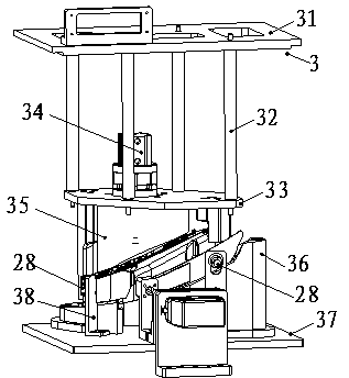
[0009] A rear lamp detection fixture for a vehicle light airtight tester. The rear lamp test fixture 3 of the vehicle light airtight tester includes four small uprights 32 on the lower surface of the top plate 31 of the rear lamp fixture. The lower end of the small column 32 is connected to the middle template 33, the upper plane of the middle template 33 is equipped with a pressurizing cylinder 34, the lower plane of the middle template 33 is installed with a semi-closed top mold 35, and the lower part of the semi-closed top mold 35 is the left bottom right ...


PUM


Abstract

The invention discloses a rear automobile lamp detecting clamp of an automobile lamp air tightness detecting machine. The rear automobile lamp detecting clamp of an automobile lamp air tightness detecting machine comprises four small vertical columns installed on the bottom surface of a rear automobile lamp clamp top plate. The bottom ends of the four small vertical columns are connected with an intermediate template. A pressurization cylinder is installed on the top surface of the intermediate template. A semi-enclosed top die is installed on the bottom surface of the intermediate template and has a low left bottom and a right high bottom. Two V-shaped bosses are disposed on corresponding positions on the bottom of the semi-enclosed top die. The V-shaped openings of the two V-shaped bosses face each other. The two V-shaped bosses are fixed on the rear automobile lamp clamp bottom plate of the rear automobile lamp detecting clamp. Two leakage detecting inductor supports are disposed on the rear automobile lamp clamp bottom plate. An inert gas inductor is installed on the leakage detecting inductor supports. With the above manner, the rear automobile lamp detecting clamp of an automobile lamp air tightness detecting machine may fast detect the air tightness of the automobile lamps, increase production yield, and decrease human cost so as to directly reduce production cost.

Description

Technical field [0001] The invention relates to the field of automated machinery, in particular to a rear lamp detection fixture of a lamp air tightness tester. Background technique [0002] In modern industrial manufacturing, many complex machines are assembled by humans, including mobile phones and computers in the electronics industry, as well as automobile manufacturing and other household appliances; these industrial manufacturing require many small assemblies The links are combined and completed together, such as the welding of car lights in automobile production. The car lights are parts that are exposed outside the car body. They will be covered by a large amount of water when it rains and when the car is washed. This has an effect on the airtightness of the lights. Certain requirements. In the past production process, there was no such tightness test. Only manual control and visual inspection during production and welding are required. After the quality requirements are ...

Claims


Application Information

Patent Timeline
Patent Type & Authority Applications(China)
IPC IPC(8): G01M3/20
Inventor 潘丽
Owner 苏州恩意精密机械有限公司
Features
  • R&D
  • Intellectual Property
  • Life Sciences
  • Materials
  • Tech Scout
  • Unparalleled Data Quality
  • Higher Quality Content
  • 60% Fewer Hallucinations
Learn More