Middle connection structure of tubular busbar

A connection structure and intermediate connector technology, applied in the direction of semi-enclosed busbar devices, etc., can solve the problems of small contact surface, high difficulty, inconvenient operation, etc., to improve stability, avoid relative rotation, and increase the contact surface area. big effect

Inactive Publication Date: 2014-03-05
上海振大电器成套集团有限公司
View PDF6 Cites 3 Cited by
  • Summary
  • Abstract
  • Description
  • Claims
  • Application Information

AI Technical Summary

Problems solved by technology

Many domestic manufacturers currently use intermediate connectors with smooth inner and outer walls. The contact surface between the intermediate connector and the pip

Method used


Image

  • Middle connection structure of tubular busbar
  • Middle connection structure of tubular busbar
  • Middle connection structure of tubular busbar

Examples


Embodiment Construction

[0027] The invention discloses an intermediate connection structure of pipe busbars, which simplifies the connecting process of pipe busbars.

[0028] The technical solutions in the embodiments of the present invention will be clearly and completely described below in conjunction with the accompanying drawings in the embodiments of the present invention. Obviously, the described embodiments are only some, not all, embodiments of the present invention. Based on the embodiments of the present invention, all other embodiments obtained by persons of ordinary skill in the art without making creative efforts fall within the protection scope of the present invention.

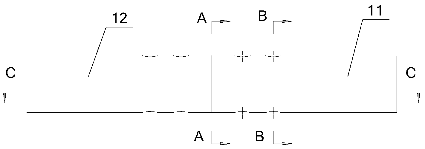
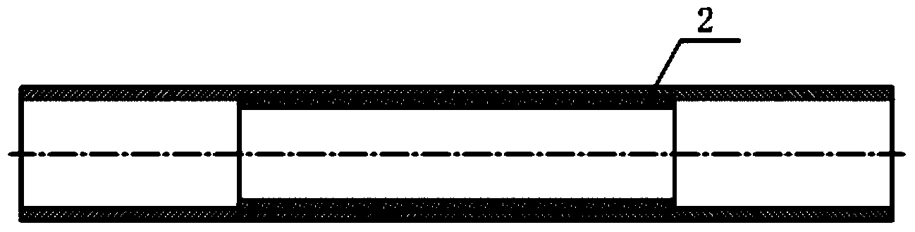
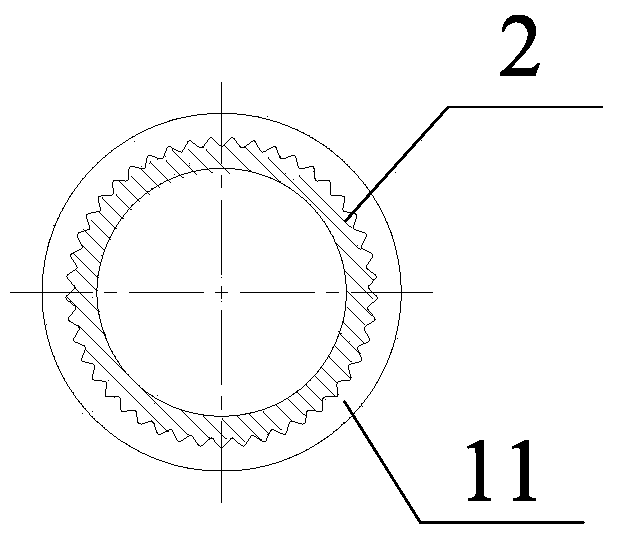
[0029] Such as Figure 1-Figure 4 as shown, figure 1 A schematic diagram of the first preferred intermediate connection structure of the pipe busbar provided by the present invention; figure 2 for figure 1 The cross-sectional view of C-C direction in the middle; image 3 for figure 1 The cross-sectional view of A...


PUM


Abstract

The invention provides a middle connection structure of a tubular busbar, and aims to achieve connection of two tubular busbars. The tubular busbars are connected by a middle connector; two ends of the middle connector are respectively sheathed by the two tubular busbars; the middle connector is a tubular structure corresponding to the tubular busbars; when the middle connector and the tubular busbars are connected, the middle connector is sheathed inside the tubular busbars to form a connection structure, or one end of each tubular busbar is extended into the middle connector to form a connection structure; a pipe sleeve structure formed between the middle connector and the tubular busbars is a circumferential contact surface; the contact surfaces between the middle connector and the two tubular busbars are provided with locking screws along the length direction of the middle connector; the locking screws enable the contact surface area to increase between the middle connector and the tubular busbars; the tight fit is realized; relative rotation between the middle connector and the tubular busbars is avoided in a stress process; and the stability of connection is improved.

Description

technical field [0001] The invention relates to the technical field of electric equipment, and more specifically, relates to an intermediate connection structure of pipe busbars. Background technique [0002] The pipe bus is mainly used in the conductor connection between the power grid transmission wire and the substation transformer in the electric power construction project, the jumper in the transmission line, the connecting conductor in the power equipment and the overcurrent conductor in the high-current DC ice melting device. It replaces the traditional The new conductors of rectangular, slotted, rod-shaped busbars and flexible wires are one of the key equipment (materials) in power transmission and transformation systems, and play a vital role in the safe and reliable operation of power transmission and transformation systems and power equipment role. [0003] The connection of the tube bus is an important part of the tube bus technology. Many domestic manufacturer...

Claims


Application Information

Patent Timeline
IPC IPC(8): H02G5/04
Inventor 孙爱勤夏敏付桂德
Owner 上海振大电器成套集团有限公司
Why Eureka
Try Eureka