
Time delay dynamic regulation method for tree structure covered with depth signals

A tree structure, signal coverage technology, applied in the direction of optical fiber radio, optical fiber transmission, etc., to achieve the effect of scalable new strength, high accuracy, and short time required

Active Publication Date: 2014-03-05
WUHAN HONGXIN TELECOMM TECH CO LTD
View PDF5 Cites 13 Cited by
  • Summary
  • Abstract
  • Description
  • Claims
  • Application Information

AI Technical Summary

Problems solved by technology

[0003] The purpose of the present invention is to overcome the shortcomings and deficiencies of the prior art, aiming at signal coverage in large-area buildings, and solve the problem of time delay adjustment in signal coverage of complex tree topological structures

Method used


Image

  • Time delay dynamic regulation method for tree structure covered with depth signals
  • Time delay dynamic regulation method for tree structure covered with depth signals
  • Time delay dynamic regulation method for tree structure covered with depth signals

Examples


specific Embodiment approach

[0018] The technical solutions of the present invention will be described below in conjunction with the accompanying drawings and embodiments.

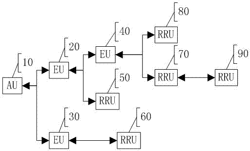
[0019] The equipment that constitutes the tree structure in the embodiment includes:

[0020] Remote Radio Unit (RRU): A low-power radio unit that provides final signal coverage and is the leaf node of the entire tree topology.

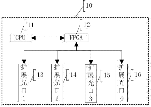
[0021] Near-end source access unit (AU): As the root of the tree topology, it is responsible for base station source access. After digital processing, it is divided into multiple channels and extended to the optical port. At the same time, the maximum delay value of the entire network is also calculated by the AU. Broadcast to all RRUs.

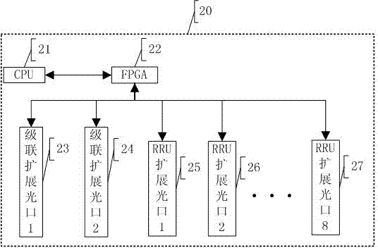
[0022] Extension unit (EU): responsible for accessing information sources from the AU side or the upper-level EU side, and plays the role of essentially managing the RRU.

[0023] The method for dynamically adjusting the delay in a tree structure provided by the embodiment...


PUM


Abstract

A time delay dynamic regulation method for a tree structure covered with depth signals includes the steps that each node in the tree structure obtains an optical fiber time delay value from a tree root node to the node, and the maximum optical fiber time delay value from the tree root node to a link final stage is recorded and serves as the maximum optical fiber link time delay of the whole network; the tree root node serves as a time delay regulation reference starting point, the tree root node broadcasts the maximum optical fiber link time delay of the whole network to various leaf nodes, the leaf nodes calculate the maximum optical fiber link time delay of the whole network and difference values Ta from the tree root node to optical fiber time delay values of the leaf nodes, the Ta and current set time delay values Ts of the Ta serve as difference values, if the absolute values of the difference values are 0 or less than a preset threshold value, regulation is needless, and otherwise the set time delay values are replaced by Ta from Ts. According to the method, the problem of time delay regulation in complex tree-shaped topological structure signal covering is solved, precision is high, time needed for whole network regulation is short, extendibility is high, and influences on time delay in a mode that a topological network adds or removes branches are reduced to the minimum.

Description

technical field [0001] The invention belongs to the technical field of telecommunication, and in particular relates to a time delay adjustment method adopted in signal coverage in near and far end digital repeaters connected by optical fibers. Background technique [0002] Each set of traditional digital optical fiber repeater consists of a near-end device AU and multiple remote radio equipment RRU connected by optical fiber. Each near-end includes multiple remote optical ports, and each remote optical port can drag a A cascaded radio frequency link formed by optical fiber physical connection at the two remote ends realizes open signal coverage for different distance areas; due to the characteristics of radio frequency signal coverage, there must be overlapping coverage areas of two or more RRUs in order to achieve no dead angle coverage , if delay adjustment is not performed, user terminals in this area may be unusable. Existing delay adjustment is mainly used in single-cha...

Claims


Application Information

Patent Timeline
Patent Type & Authority Applications(China)
IPC IPC(8): H04B10/2575
Inventor 高国庆欧文军张文成
Owner WUHAN HONGXIN TELECOMM TECH CO LTD
Learn More