Oil-gas separator

A technology of oil-gas separator and mixed gas, which is applied in separation methods, dispersed particle separation, chemical instruments and methods, etc., and can solve problems such as filter clogging and increased maintenance costs

Inactive Publication Date: 2014-03-12
GAOMI WANHE AXLE
View PDF0 Cites 2 Cited by
  • Summary
  • Abstract
  • Description
  • Claims
  • Application Information

AI Technical Summary

Problems solved by technology

The disadvantage of the oil-gas separator of this structure is that: since the mixed gas entering from the mixed gas inlet has pressure, and the mixed gas is mainly filtered by the filter screen, the filter screen is easy to be blocked when filtering, and the blockage will increase the resistance and cause the oil to pour suction, so that the lower air outlet is sprayed with oil, so the lower filter must be cleaned or replaced frequently, which increases maintenance costs

Method used


Image

  • Oil-gas separator

Examples


Embodiment Construction

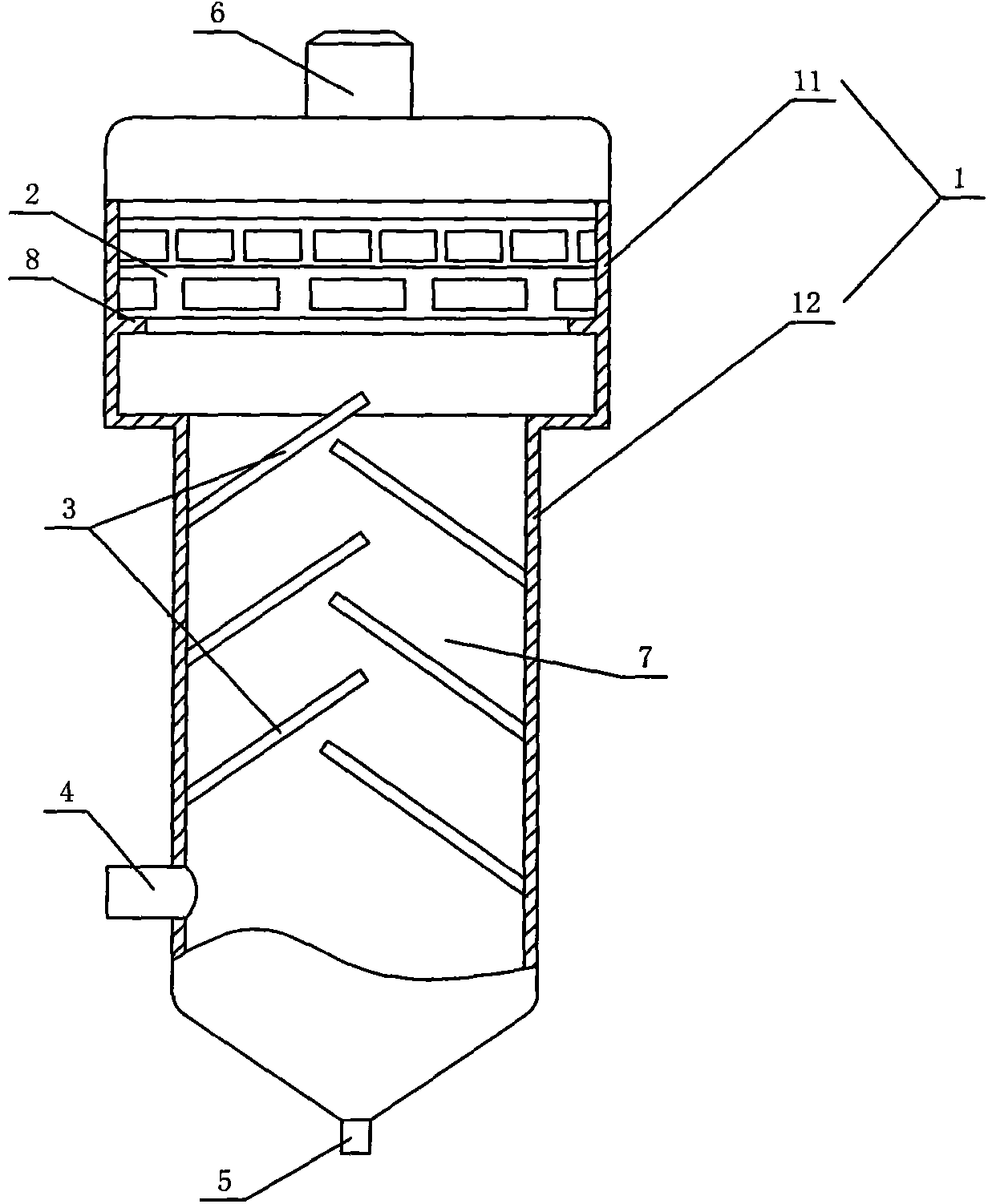
[0011] like figure 1 The shown oil-gas separator comprises a cylindrical outer shell 1, the outer shell 1 is composed of upper and lower sections with unequal diameters, the diameter of the lower shell 12 is smaller than the diameter of the upper shell 11, and the lower shell 12 The lower part of the casing is provided with a mixed gas inlet 4, the bottom is provided with an oil discharge port 5, the top of the upper casing 11 is provided with a waste gas outlet 6, and the lower part of the inner cavity of the lower casing 12 is fixed with opposite inclined upwards and arranged at staggered intervals. The multi-block baffles 3, the protruding ends of the multi-block baffles 3 are overlapped on the vertical projection, that is, the baffles 3 protrude obliquely upward from the connection end to the inner cavity of the outer shell 1, and the baffles 3 can be made of thin Made of stainless steel strips or plastic sheets, the bottom baffle 3 is located above the gas mixture inlet 4...


PUM


Abstract

The invention discloses an oil-gas separator which comprises an outer shell of which the side part is provided with a gas mixture inlet and the top is provided with an exhaust gas outlet, wherein the lower part of the inner cavity of the outer shell is fixedly provided with a plurality of baffles which obliquely protrudes upwards in opposite and are arranged at intervals in a staggered mode; the protruding ends of the baffles are overlapped on the vertical projection; the baffles divide the inner cavity of the outer shell into circuitously upward channels; the upper part of the inner cavity of the outer shell is provided with a filter screen, and the bottom of the outer shell is provided with an oil discharge outlet; the outer shell is cylindrical and is composed of an upper section and a lower section; the diameter of the lower section is smaller than that of the upper section; the baffles are installed in the lower section, and the filter screen is installed in the upper section; the inner cavity wall of the upper section is provided with an inward convex annular boss; and the filter screen is installed on the annular boss. The oil-gas separator can lower the blockage risk of the filter screen, reduce the internal resistance of the gas mixture passing through the inner cavity of the outer shell, prolong the time interval for cleaning or replacing the filter screen, and lower the maintenance cost.

Description

technical field [0001] The invention relates to an oil-gas separator. Background technique [0002] The existing oil-gas separator mainly adopts two-stage type for oil-gas separation. It includes a cylindrical outer casing, the upper part of the outer casing is provided with a mixed gas inlet, the lower part is provided with a waste gas outlet, and a centrifugal accelerator and a filter screen are arranged in the outer casing from top to bottom. The disadvantage of the oil-gas separator of this structure is that: since the mixed gas entering from the mixed gas inlet has pressure, and the mixed gas is mainly filtered by the filter screen, the filter screen is easy to be blocked when filtering, and the blockage will increase the resistance and cause the oil to pour The suction makes the lower air outlet spray oil, so the lower filter must be cleaned or replaced frequently, which increases the maintenance cost. Contents of the invention [0003] The technical problem to be ...

Claims


Application Information

Patent Timeline
IPC IPC(8): B01D50/00
Inventor 陈希昌
Owner GAOMI WANHE AXLE
Why Eureka
Try Eureka