
Permanent Magnetic Separator

A technology of permanent magnet iron remover and magnetic steel, which is applied in the fields of magnetic separation, chemical instruments and methods, solid separation, etc., can solve the problems of large power consumption, hidden danger of safety accidents, large energy consumption, etc., so as to reduce energy loss and use. Convenience and high work efficiency

Inactive Publication Date: 2016-01-27
WUXI ZHIYUDE TECH
View PDF6 Cites 0 Cited by
  • Summary
  • Abstract
  • Description
  • Claims
  • Application Information

AI Technical Summary

Problems solved by technology

It is difficult to unload iron with a large volume and weight in this way. At the same time, the safety of personnel cannot be guaranteed during use. It is not suitable for automatic control and is only suitable for use in small-scale occasions; there are also belt unloading irons, which mainly rely on The rotating belt scrapes off the iron pieces sucked up by the permanent magnets, and they can still be sucked up, but because the iron-scraping aluminum plate is narrow, it is easy to cause the sucked iron pieces to be unable to be scraped off. If a large iron-scraping aluminum plate is used, it will consume A large amount of energy requires greater power
Electromagnetic iron remover needs to consume a lot of power when it works, it is easy to generate heat, and the heat will make the enameled wire insulation varnish emit peculiar smell, thus causing the generation of PM2.5 and polluting the air
If the voltage is unstable and the heat rises, it will also cause the coil to short-circuit and burn out the machine, which is likely to cause potential safety accidents, thus increasing the operation and maintenance costs too high

Method used


Image

  • Permanent Magnetic Separator
  • Permanent Magnetic Separator

Examples


Embodiment Construction

[0015] The present invention will be described in further detail below in conjunction with the accompanying drawings.

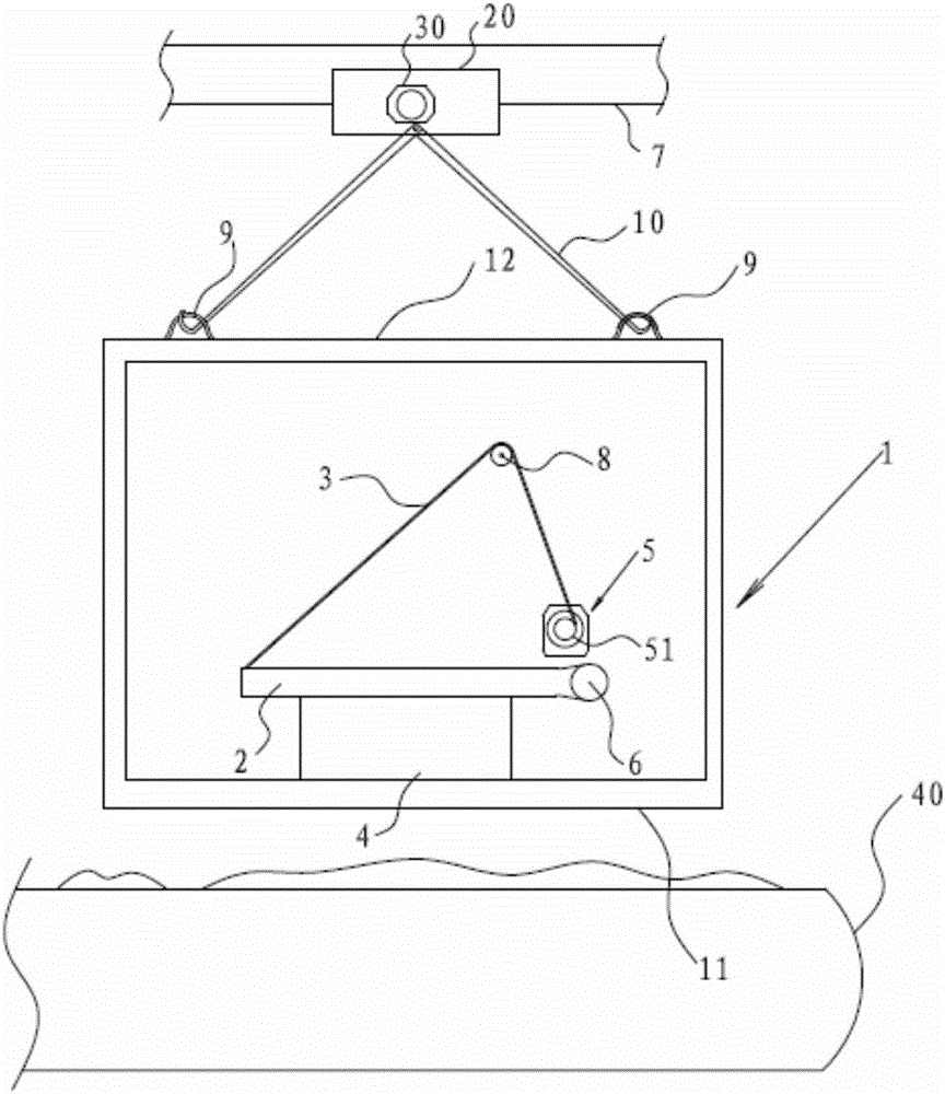
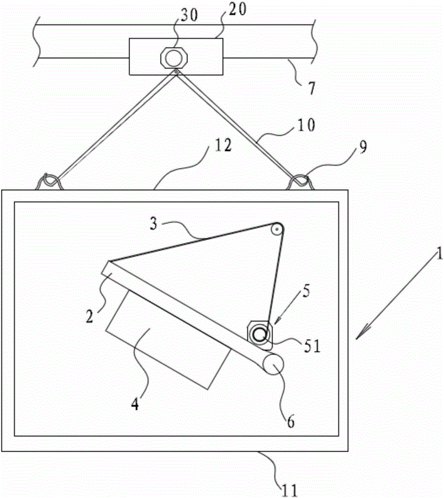
[0016] refer to figure 1 and figure 2 . The permanent magnet iron remover of the present invention includes a casing 1, a rotating shaft 6, a magnetic steel 4 and a driving device, the driving device is arranged in the casing 1, the casing 1 includes a bottom plate 11, the rotating shaft 6 is connected with the driving device, and the magnetic steel 4 is connected with the rotating shaft 6, the rotating shaft 6 and the magnetic steel 4 are both arranged in the box body 1, and the magnetic steel 4 is arranged correspondingly to the bottom plate 11. The driving device drives the rotating shaft 6 to rotate, and the magnetic steel 4 rotates along with the rotating shaft 6 . Therefore, it can be realized that after the magnetic force of the magnet 4 makes the iron filings outside the base plate 11 adsorb, with the rotation of the magnet 4, the magnetic force l...


PUM


Abstract

The invention discloses a permanent magnetic iron remover. The iron remover comprises a box body, a rotating shaft, a magnetic steel and a driving device, wherein the driving device is arranged in the box body; the rotating shaft is connected with the driving device; the box body comprises a base plate; the magnetic steel is connected with the rotating shaft; the magnetic steel and the rotating shaft are both arranged in the box body; the magnetic steel is arranged corresponding to the base plate. When the magnetic steel adsorbs external scrap iron through the base plate, the magnetic steel is rotated along with the rotating shaft, the magnetic line of the magnetic steel transfers, namely the magnetic line direction acting on the scrap iron is changed; when the magnetic force acting on the scrap iron is vanished or the magnetic force is smaller than gravity of the scrap iron, the scrap iron falls off from the base plate. The permanent magnetic iron remover can realize scrap iron falling off through transfer of the magnetic line of the magnetic steel. The permanent magnetic iron remover is low in energy consumption, convenient to use, high in working efficiency, and suitable for automatic control.

Description

technical field [0001] The invention belongs to a permanent magnet and electromagnetic iron remover, in particular to a permanent magnet iron remover. Background technique [0002] At present, there are two main types of permanent magnet and electromagnetic iron remover. The current permanent magnet iron remover mainly relies on manual hand to pull iron from the permanent magnet, and it is still in the stage of manual iron removal. It is difficult to unload iron with a large volume and weight in this way. At the same time, the safety of personnel cannot be guaranteed during use. It is not suitable for automatic control and is only suitable for use in small-scale occasions; there are also belt unloading irons, which mainly rely on The rotating belt scrapes off the iron pieces sucked up by the permanent magnets, and they can still be sucked up, but because the iron-scraping aluminum plate is narrow, it is easy to cause the sucked iron pieces to be unable to be scraped off. If ...

Claims


Application Information

Patent Timeline
Patent Type & Authority Patents(China)
IPC IPC(8): B03C1/18
Inventor 惠松吴旭民
Owner WUXI ZHIYUDE TECH
Learn More