Small-end connected selection equipment for convenient chopsticks
A convenient, conjoined technology, applied in sorting and other directions, can solve the problems of increased cost of convenient chopsticks, differences in convenience chopsticks, low efficiency, etc., and achieves the effect of high degree of automation, reduced labor intensity, and improved work efficiency.
- Summary
- Abstract
- Description
- Claims
- Application Information
AI Technical Summary
Problems solved by technology
Method used
Image

Examples
Embodiment Construction
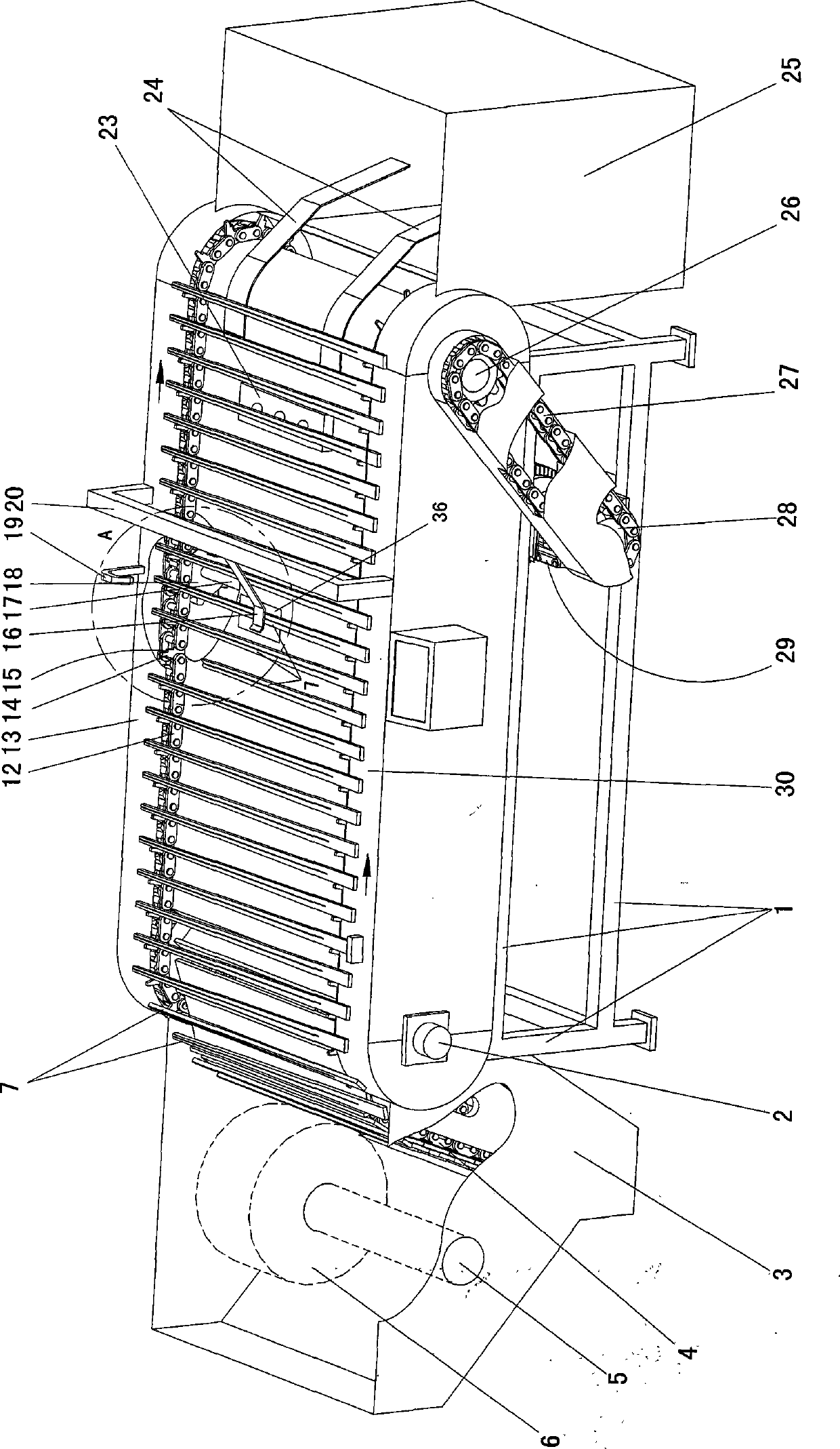
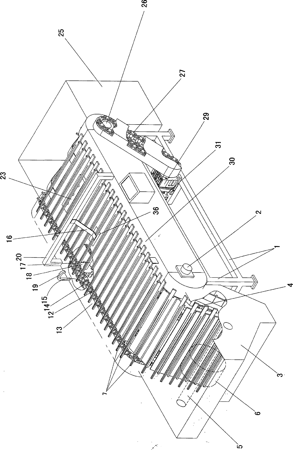
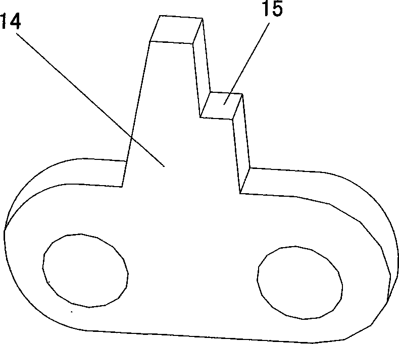
[0016] Such as figure 1 , 2 , Shown in 3, 4, 5: 1 is a frame, which can be made by welding section steel. The driven shaft 2 and the driving shaft 26 connected to the driving mechanism are supported on the frame 1 by bearings. Both the driving shaft 26 and the driven shaft 2 are equipped with sprockets and are equipped with a double row of transmission for convenient chopsticks 7. chain12. On the chain plate that forms each transmission chain 12, be provided with the symmetrical protruding portion 14 that is used to promote convenient chopsticks 7 to move forward, promptly on the inner chain plate of every row of chains 12, there is a protruding part integrated with the chain plate, Protrusions 14 are formed.
[0017] Be positioned at the outside of transmission chain 12 on frame 1 and be respectively provided with the left sliding platform 13 and the right sliding platform 30 of support convenient chopsticks 7, conveying chain 12 is lower than the upper plane of left slidi...
PUM
 Abstract
Description
Claims
Application Information